Optical connector plug and optical connector

a technology of optical connectors and plugs, which is applied in the direction of optics, instruments, optical light guides, etc., can solve the problems of reducing affecting the safety of use, and affecting the operation of the optical connection of the optical fiber. , to achieve the effect of reducing the manufacture cost and the introduction cost, and enhancing the safety

Inactive Publication Date: 2006-08-22
SEIKOH GIKEN
View PDF2 Cites 35 Cited by
  • Summary
  • Abstract
  • Description
  • Claims
  • Application Information

AI Technical Summary

Benefits of technology

[0014]The present invention has been made in view of the above, and an object of the present invention is therefore to provide an optical connector plug and an optical connector which are enhanced in safety by blocking, readily and without fail, light radiated from an optical fiber and which are reduced in manufacture cost and introduction cost.
[0015]To attain the above object, according to a first aspect of the present invention, there is provided an optical connector plug including: a plug frame for holding a ferrule in which an optical fiber is held; a plug housing having a plug frame holding hole in which the plug frame is held in a manner that allows the plug frame to move axially, the plug frame holding hole piercing through the entire length of the plug housing; a shielding plate whose proximal end is held to one side of an inner surface of the plug frame holding hole of the plug housing in a manner that allows the shielding plate to tilt, and whose distal end moves between a shielding position, at which the shielding plate shields a front end face of the ferrule, and an unshielding position, at which the shielding plate allows the plug frame to move; an operating plate whose proximal end is held, in a tiltable manner, to the one side of the inner surface of the plug frame holding hole at a position nearer to the center of the optical connector plug than the shielding plate, and whose distal end is in contact with or is engaged with the shielding plate to tilt along with the shielding plate, the plug frame being capable of retracting, upon movement of the shielding plate to the shielding position, to a housing position at which no interference occurs with the shielding plate and the operating plate; and biasing and holding means for biasing and positioning the shielding plate and the operating plate in a manner that brings the shielding plate to the shielding position as the plug frame moves to the housing position, the optical connector being characterized in that when the plug frame is moved toward a front end of the plug housing, the operating plate is tilted by this movement of the plug frame, and the tilted operating plate pushes the shielding plate to the unshielding position, allowing the plug frame to move to an optical connection position with respect to the plug housing.

Problems solved by technology

According to the optical connection of the optical fibers by fusion-welding, there arises a problem that attachment and detachment of the optical connection of the optical fibers cannot be carried out.
There also arises a problem that fusion-welding steps are complicated which gives rise to a problem that there is a restriction in use thereof.
A problem of any SC type, MU type, or like other conventional optical connector plug is that light is radiated from the front end face of an optical fiber it holds since the light could be hazardous to human health if radiated for a certain period of time onto human body, especially a localized area such as an eye.
While a particularly high level of safety is required of an optical connector plug that holds the tip of an optical fiber that is led inside a house by FTTH or the like, common SC type, MU type, or other optical connector plugs currently used in FTTH have no preventive measures against light radiation and accordingly contain a hazard to health.
The risk of harming human body with light irradiated from the tip of an optical fiber is increasing with the increase in output power of optical communications.
However, a drawback of the optical connector plug having a cover is that the cover, which is placed and operated on an outer wall of the optical connector plug, gives the optical connector plug contours different from those of conventional optical connector plugs.
The unusually shaped optical connector plug makes it necessary for an optical connector adapter, which connects two optical connector plugs with each other face-to-face, to have a shape different from its conventional shape in conformity with the unique shape of the optical connector plug, thereby raising the manufacture cost.
The optical connector plug having a cover also requires a new specification separate from the existing one for SC type, MU type, and other conventional optical connector plugs, meaning that it is incompatible with SC type, MU type, and other conventional optical connector plugs.

Method used


Image

  • Optical connector plug and optical connector
  • Optical connector plug and optical connector
  • Optical connector plug and optical connector

Examples


first embodiment

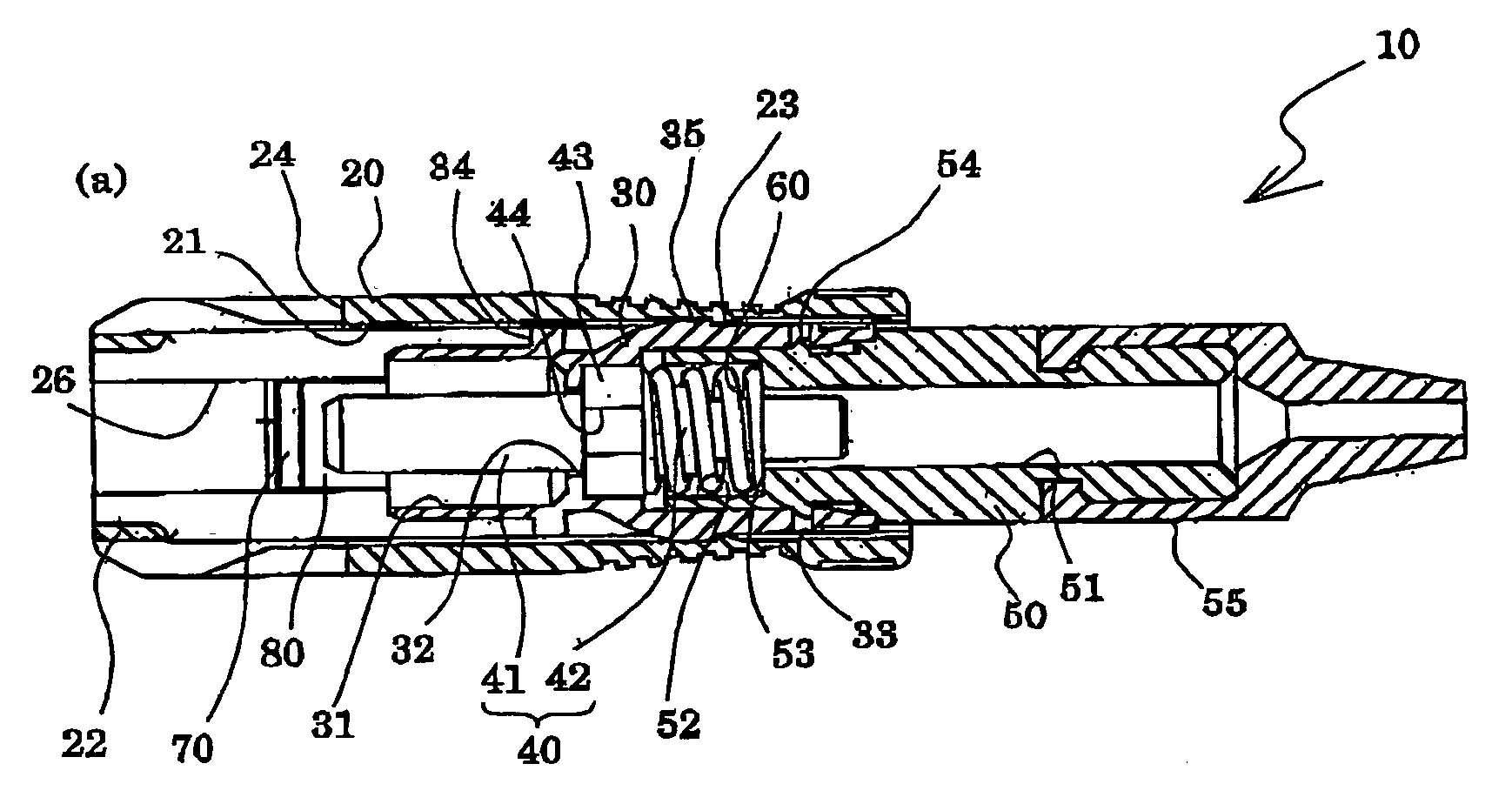
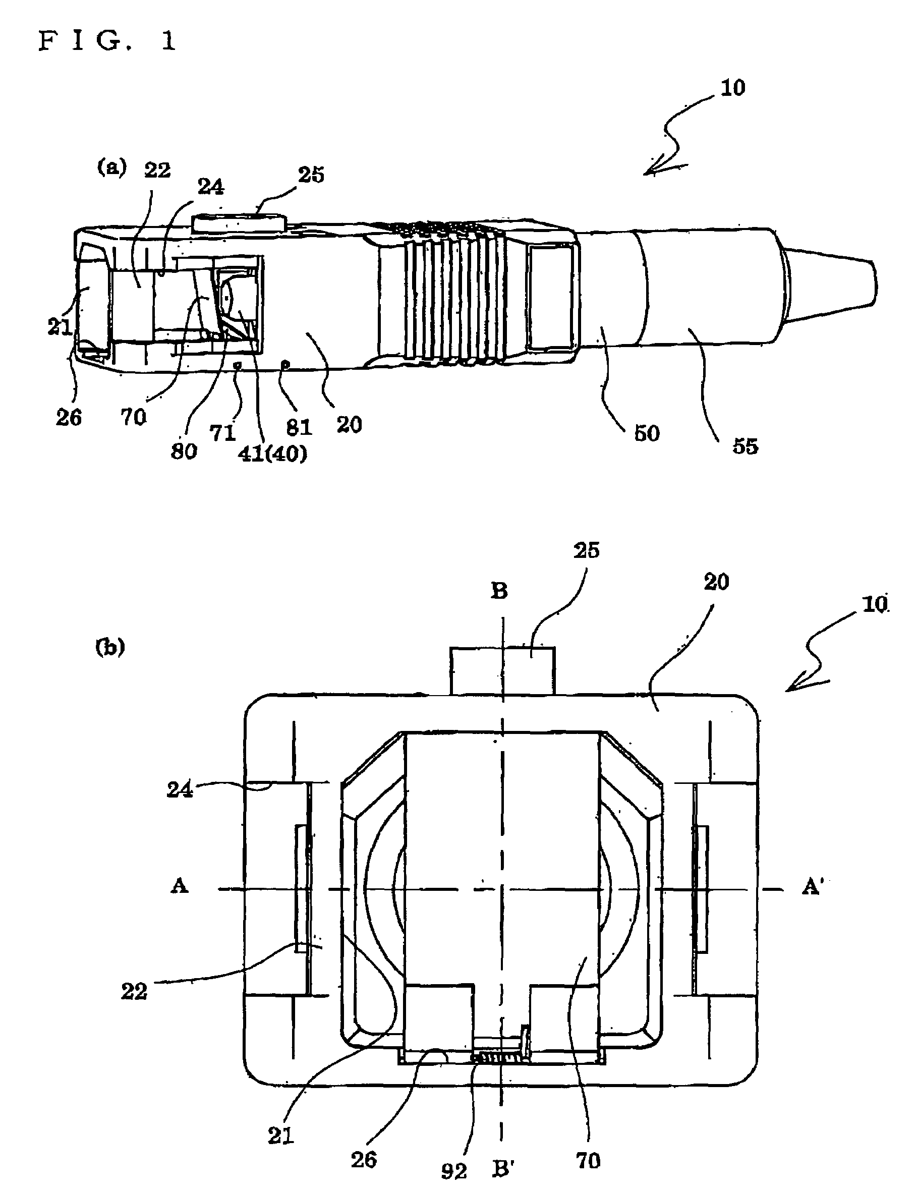
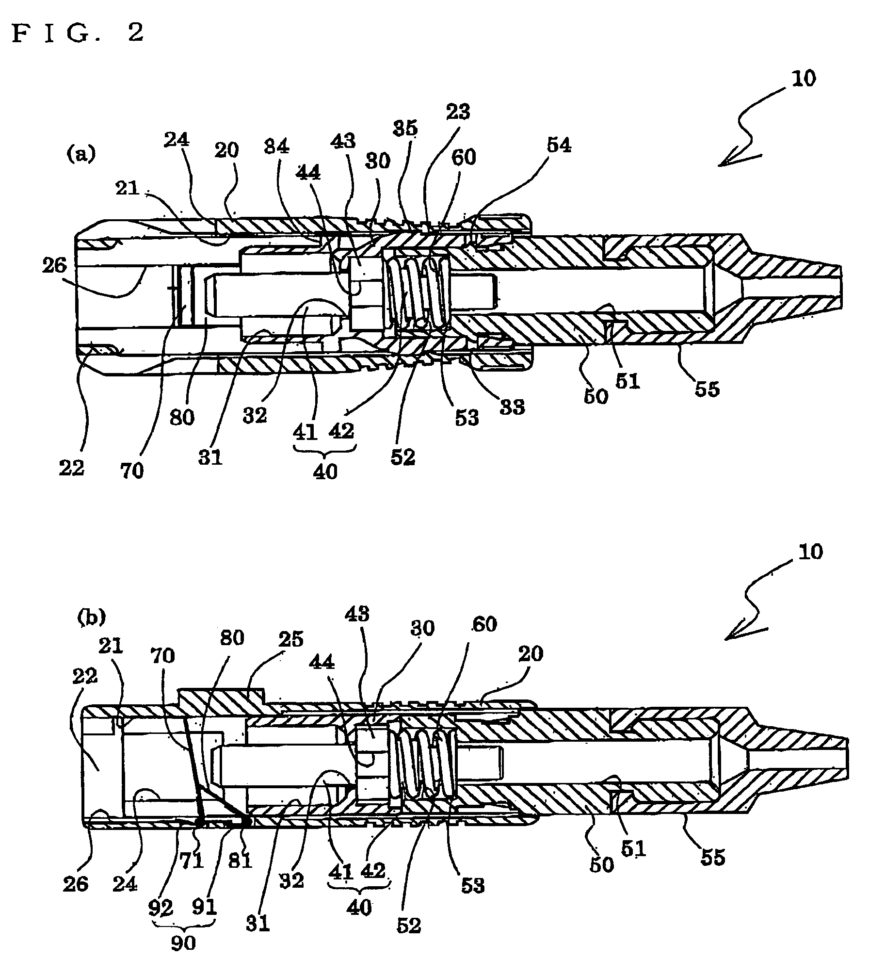
[0027]FIGS. 1A and 1B are a perspective view of an optical connector plug according to a first embodiment of the present invention and a plan view of the same, respectively. FIGS. 2A and 2B are sectional views taken along the lines A–A′ and B–B′ of FIG. 1B, respectively.

[0028]As shown in the drawings, an optical connector plug 10 of this embodiment has a plug housing 20, which is fit in an SC type optical connector adapter, a plug frame 30, which is held in the plug housing 20 in a manner that allows the plug frame 30 to move in the axial direction, a ferrule 40, which holds optical fibers to be connected optically and which is inserted from the back of the plug frame 30, a stop ring 50, whose front end engages with the rear end of the plug frame 30, and a biasing spring 60, which is held between the ferrule 40 and the stop ring 50 to bias the ferrule 40 toward the front end in the axial direction.

[0029]The ferrule 40 is, as shown in FIGS. 2A and 2B, composed of a ferrule cylindrica...

second embodiment

[0078]FIGS. 4A and 4B are a perspective view of an optical connector plug according to a second embodiment of the present invention and a plan view of the same, respectively. FIGS. 5A and 5B are sectional views of a main part, and are taken along the lines C–C′ and D–D′ of FIG. 4B, respectively. In this embodiment, members identical to those of the above embodiment are denoted by the same symbols and descriptions on such members will not be repeated.

[0079]As shown in the FIGS. 4A and 4B and FIGS. 5A and 5B, an optical connector plug 10A has a plug housing 20A in which the plug frame 30 similar to the one in the above-described first embodiment is held in a movable manner. The plug frame 30 holds the ferrule 40, the stop ring 50, and a biasing spring (not shown).

[0080]The plug housing 20 has the plug frame holding hole 21. Proximal ends of a shielding plate 70 and an operating plate 80A are held through the shielding plate axis 71 and the operating plate 81, respectively, to one side...

third embodiment

[0089]FIGS. 6A and 6B are a perspective view of an optical connector plug according to a third embodiment of the present invention and a plan view of the same, respectively. FIGS. 7A and 7B are sectional views of a main part, and are taken along the lines E–E′ and F–F′ of FIG. 6B, respectively. In this embodiment, members identical to those of the above embodiments are denoted by the same symbols and descriptions on such members will not be repeated.

[0090]As shown in the FIGS. 6A and 6B and FIGS. 7A and 7B, an optical connector plug 10B has a plug housing 20B in which the plug frame 30 similar to the one in the above-described first embodiment is held in a movable manner. The plug frame 30 holds the ferrule 40, the stop ring 50, and a biasing spring (not shown).

[0091]The plug housing 20B has the plug frame holding hole 21. Proximal ends of a shielding plate 70B and an operating plate 80B are held through the shielding plate axis 71 and the operating plate axis 81 in a tiltable manne...


PUM


Abstract

Provided are an optical connector plug and an optical connector, including: a shielding plate which is held in a plug frame holding hole of a plug housing in a manner that allows the shielding plate to tilt, the distal end of the shielding plate moving between a shielding position and an unshielding position; an operating plate which is held in a tiltable manner in the plug frame holding hole and adapted to tilt along with the shielding plate, the plug frame being capable of retracting, upon movement of the shielding plate to the shielding position, to a housing position at which no interference occurs with the shielding plate and the operating plate; and a biasing and holding member for biasing and positioning the shielding plate and the operating plate in a manner that brings the shielding plate to the shielding position as the plug frame moves to the housing position. When the plug frame is moved toward a front end of the plug housing, the operating plate is tilted by this movement of the plug frame, and the tilted operating plate pushes the shielding plate to the unshielding position, thus allowing the plug frame to move to an optical connection position with respect to the plug housing.

Description

BACKGROUND OF THE INVENTION[0001]1. Field of the Invention[0002]The present invention relates to an optical connector plug and an optical connector for holding a front end of an optical fiber and optically connecting the optical fibers.[0003]2. Description of the Related Art[0004]Conventionally, optical connection of optical fibers used in optical communication or the like is carried out by a method of using an optical connector having an optical connector plug holding a front end of the optical fiber and an optical connector adapter for carrying out optical connection of the optical fibers by fixing the optical connector plugs, or a method of fusion-welding front end faces of the optical fibers.[0005]According to the optical connection of the optical fibers by fusion-welding, there arises a problem that attachment and detachment of the optical connection of the optical fibers cannot be carried out. There also arises a problem that fusion-welding steps are complicated which gives ri...

Claims


Application Information

Patent Timeline
Patent Type & Authority Patents(United States)
IPC IPC(8): G02B6/36G02B6/38
CPCG02B6/3849G02B2006/4297G02B6/3893
Inventor TAIRA, JUNJIARAI, NORIMASAMINAMI, KOUJI
Owner SEIKOH GIKEN
Why Eureka
Try Eureka