Motor and drive control system thereof

a technology of motor and control system, applied in the direction of dynamo-electric converter control, motor/generator/converter stopper, magnetic circuit shape/form/construction, etc., can solve the problems of motor enlarged and mass in comparison to generated torque, and achieve the effect of superior torque and weight balan

Inactive Publication Date: 2006-08-22
GK BRIDGE 1
View PDF20 Cites 21 Cited by
  • Summary
  • Abstract
  • Description
  • Claims
  • Application Information

AI Technical Summary

Benefits of technology

[0009]Nevertheless, with the motor explained in the description of the related art, the weight became massive in comparison to the generated torque, and there is a problem in that the motor would become enlarged when attempting to increase the generated torque. Thus, an object of the present invention is to provide a motor suitable for miniaturization and superior in torque and weight balance.

Problems solved by technology

Nevertheless, with the motor explained in the description of the related art, the weight became massive in comparison to the generated torque, and there is a problem in that the motor would become enlarged when attempting to increase the generated torque.

Method used


Image

  • Motor and drive control system thereof
  • Motor and drive control system thereof
  • Motor and drive control system thereof

Examples


Embodiment Construction

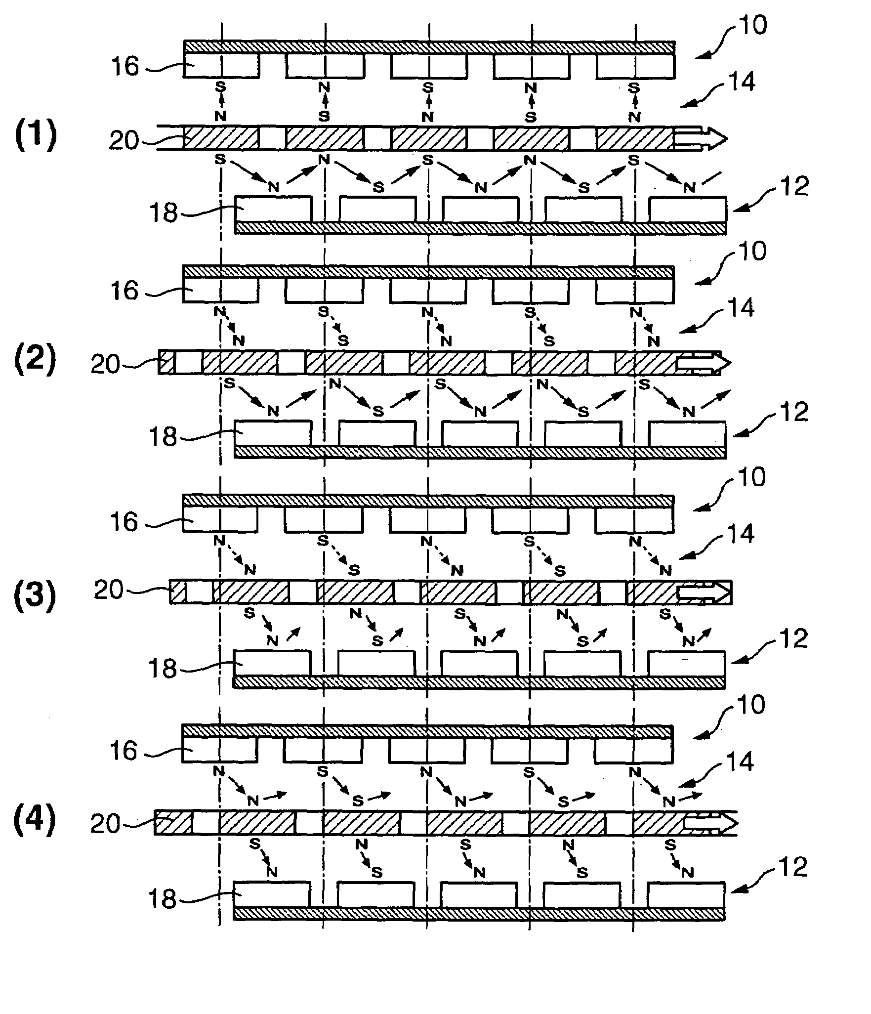
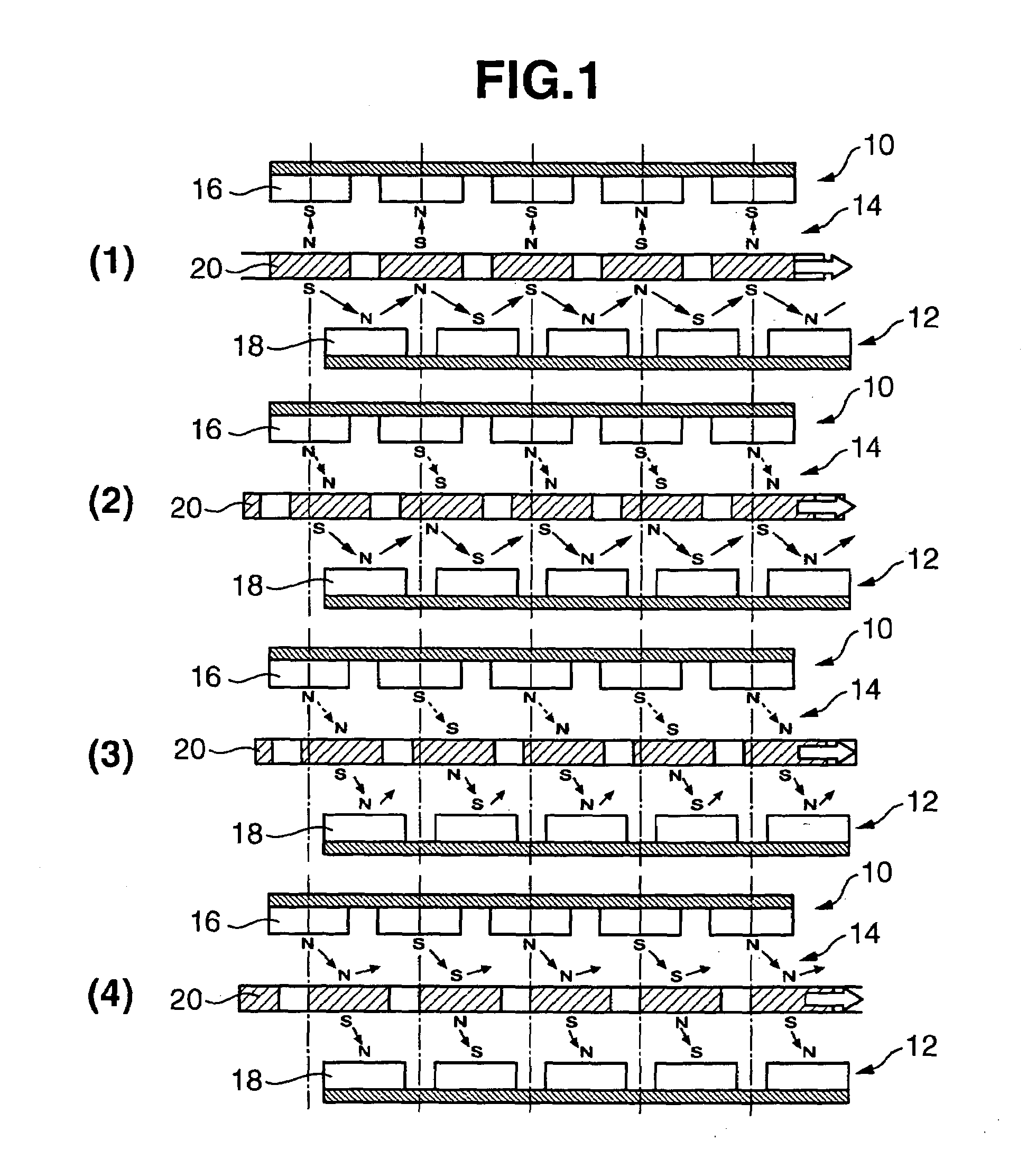
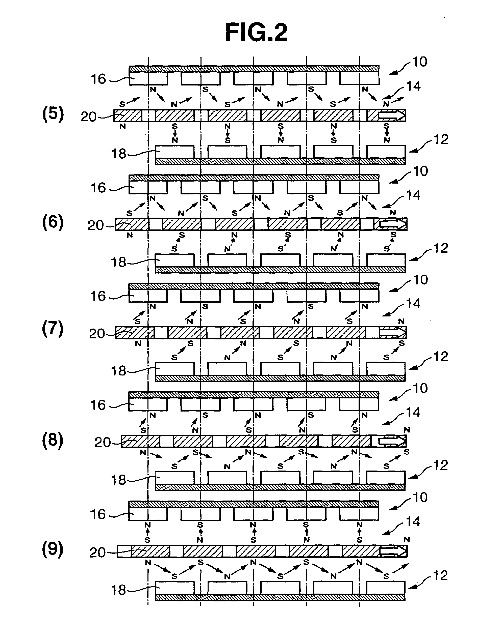
[0040]FIG. 1 and FIG. 2 are diagrams showing the principal of operation of the motor pertaining to the present invention. This motor has a constitution where a third permanent magnet 14 is interposed between a first coil pair (A phase coil) 10 and a second coil pair (B phase coil) 12. The coils and permanent magnet may be constituted circularly (arc, circle) or linearly. When formed circularly, either the permanent magnet or the coil phase functions as the rotor, and, when formed linearly, one of the above becomes a slider.

[0041]A first coil pair 10 comprises a constitution in which the coils 16 alternately excitable to the opposite poles are sequentially aligned in a prescribed spacing, preferably an even spacing. FIG. 5 is an equivalent circuit diagram of this first coil pair. According to FIG. 1 and FIG. 2, as described later, with a two-phase excitation coil, all coils are excited to be constantly driven against the two-phase exciting coil during the start-up rotation (2π) with ...


PUM


Abstract

Provided is a motor having a magnetic polar unit in which a permanent magnetic polar array having arranged therein alternately a plurality of permanent magnetic polar elements in alternate opposite poles is made to face a plurality of electromagnetic coil arrays alternately excited at opposite poles, and the permanent magnetic polar array is made to move thereby; wherein the motor further comprises a sensor for detecting the periodical magnetic change accompanying the movement of the permanent magnetic polar array, the output of the sensor is directly returned as a direct drive waveform to the electromagnetic coils, and this drive circuit forms the excitation signal based on the return signal.

Description

RELATED APPLICATIONS[0001]This application claims priority to Japanese Patent Application No. 2004-071417 filed Mar. 12, 2004 which is hereby expressly incorporated by reference herein in its entirety.[0002]1. Field of the Invention[0003]The present invention relates to various motors constituted to rotate a rotor or move a slider formed from a permanent magnet or ferromagnetic material by linearly arranging coils that generate magnetic poles and sequentially switching the current to be applied to the coil, a magnetic structure to be employed in such a motor, and a power driver employing this motor as its drive source. The present invention may be employed in the likes of an electric vehicle, electric cart and electric wheelchair, as well as an electric toy, electric airplane, small electronic appliances and MEMS as the foregoing power driver.[0004]2. Description of the Related Art[0005]An AC motor driven with a frequency signal such as an alternating current can be broadly classifi...

Claims


Application Information

Patent Timeline
Patent Type & Authority Patents(United States)
IPC IPC(8): H02K1/22G05B11/28H02K11/00H02K23/66H02K29/08H02K3/00H02K21/00H02K41/03H02P3/18H02P6/06H02P6/08H02P6/24H02P7/00H02P25/06H02P25/064
CPCH02P6/16H02P6/002H02P6/28
Inventor TAKEUCHI, KESATOSHI
Owner GK BRIDGE 1
Why Eureka
Try Eureka