Backlighting system for display screen

a backlighting system and display screen technology, applied in the field of display devices, can solve the problems of power loss, power waste through current, and need to incorporate cooling components

Inactive Publication Date: 2006-08-22
APTIV TECH LTD
View PDF4 Cites 91 Cited by
  • Summary
  • Abstract
  • Description
  • Claims
  • Application Information

AI Technical Summary

Problems solved by technology

This support circuitry and the tubes generate excess heat within the display apparatus and due to the proximity of the power supply wires required, power is wasted through currents produced as a result of parasitic capacitive coupling.
These problems result in a need to provide a relatively high capacity and quality power supply in existing backlit display apparatus and often also results in the need to incorporate cooling components to remove the excess heat produced.
Two wires are required per lamp which results in a large number of wires which is cumbersome, messy, produces excessive Electromagnetic Interference (EMI) and results in power loss through the above mentioned capacitive coupling, particularly in MLD units because of the increased number of lamps.
This system allows two wires to be used to supply power to all of the lamps in a backlighting system but results in bright and dark spots and variance as power can not be regulated easily to ensure that each lamp receives the same amount of power.
Power is also lost in this system due to the introduced parasitic capacitance between the supply wires and the metallic enclosure which is required.
Furthermore, the system disclosed requires higher rated electronic components such as inverters which are physically larger and more expensive.

Method used


Image

  • Backlighting system for display screen
  • Backlighting system for display screen
  • Backlighting system for display screen

Examples


Embodiment Construction

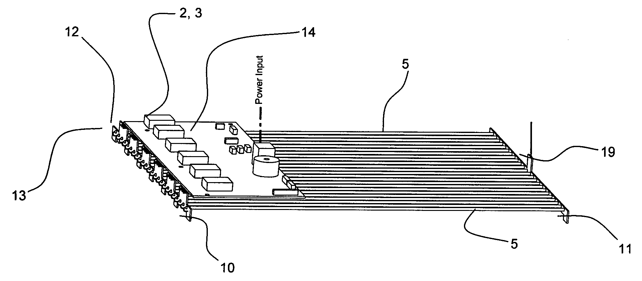
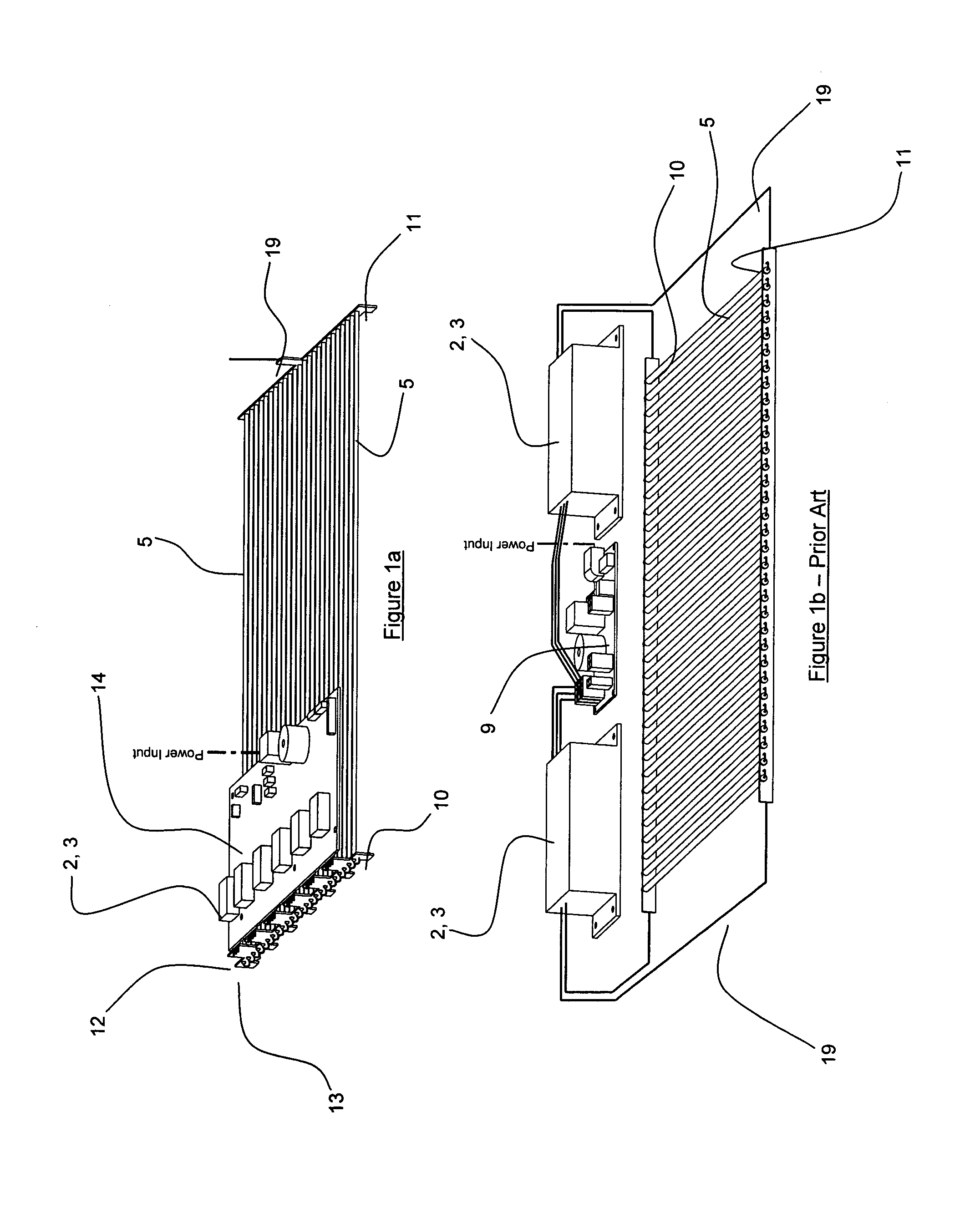
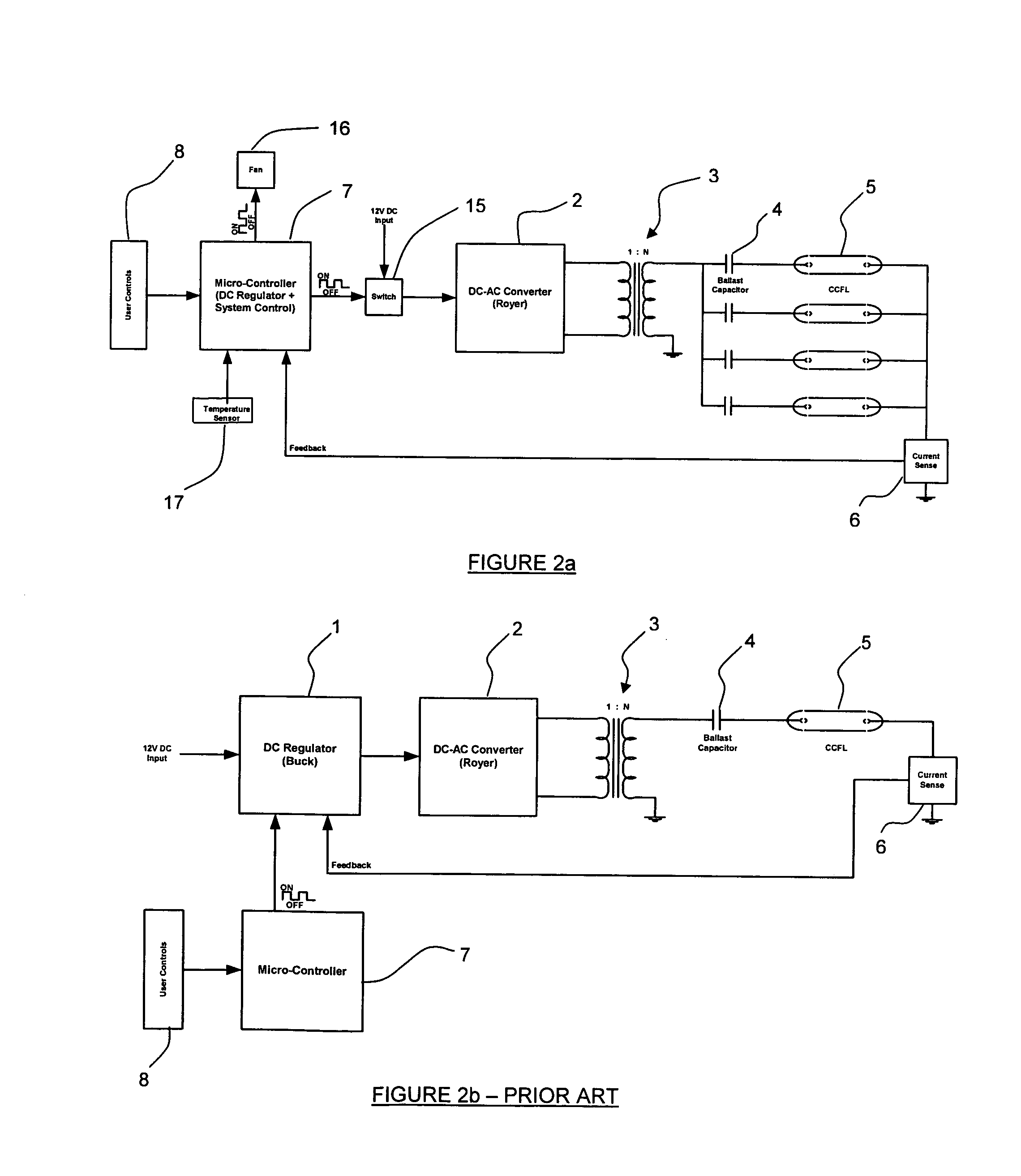
[0055]With reference initially to FIGS. 1b and 2b, examples of a backlighting system and basic circuit block diagram according to the prior-art for controlling the power distribution to a series of light sources such as fluorescent lamps, and in particular Cold Cathode Fluorescent Tubes (CCFT) or lamps, are shown. The prior-art backlighting system includes a regulator 1 which receives DC input power and controls the amount of this input power fed to a royer 2. The royer 2 converts the DC voltage output by regulator 1 to an AC voltage which is boosted by a transformer 3. Commonly, the combination of royer and transformer is known as an inverter.

[0056]A ballast capacitor 4 is positioned between the secondary side of the transformer and one end of the or each lamp 5 and is required In order to establish a starting voltage and make the lamp appear as a linear electrical load to the regulator / royer combination. Regulator 1 enables the backlighting system to regulate or control the bright...


PUM

PropertyMeasurementUnit
temperatureaaaaaaaaaa
lamp currentaaaaaaaaaa

Abstract

A circuit board (14) on which the electronic components (2,3) providing power to a series of light sources (6) is positioned as near as possible to light sources in order to minimise parasitic energy losses which would be introduced by lengths of wiring. The light sources (5) are usually elongate tubular Cold Cathode Fluorescent Tubes arranged parallel to one another in a single plane and the circuit board (14) may be mounted directly over the light sources, towards one end of the tubes. Standard PCB board-to-board connectors (12) may be provided at an edge of the circuit board (14) and a further circuit board (10) provided with a series of conductive tracks may provide both a mechanical and electrical connection between the circuit board (14) and the light sources (5). A power distribution method is also disclosed in which both current and temperature of the light sources are monitored and regulated in order to extend the lifetime of the light sources (5) and to stabilize their brightness.

Description

TECHNICAL FIELD[0001]This invention relates to display apparatus and in particular, though not solely, to the backlighting system employed in display apparatus such as LCD display screens, more particularly, multi-layer display (MLD) screens.BACKGROUND ART[0002]Certain types of display apparatus, such as Liquid Crystal Display (LCD) screens used as computer screens or television screens, require backlighting in order to make display elements on the screen visible, or more easily visible, to a viewer of the display unit.[0003]Existing “flat” screen display units, for example LCD display screens, may be single-layer display (SLD) units having a single display layer or single planar array of liquid crystal pixels, or multi-layer display (MLD) units in which a number of planar arrays of LCD pixels are aligned in a stacked or sandwiched arrangement. Multi-layered display (MLD) units provide a significant improvement over existing single layer display (SLD) units or displays. MLD units ma...

Claims


Application Information

Patent Timeline
Patent Type & Authority Patents(United States)
IPC IPC(8): H05B37/00G02F1/1335G02F1/133H05B41/282H05B41/392H05K1/14
CPCH05B41/3927H05B41/2828G02F1/133604H05K1/141G02F1/133
Inventor EMSLIE, JAMES STEPHENPEASE, RICHARD WILLIAM
Owner APTIV TECH LTD
Why Eureka
Try Eureka