Superconducting driver circuit

a driver circuit and superconducting technology, applied in pulse generators, pulse techniques, instruments, etc., can solve the problems of malfunction operation and capacitance formation, and achieve the effect of longer charge and discharge tim

Inactive Publication Date: 2006-08-22
INT SUPERCONDUCTIVITY TECH CENT
View PDF5 Cites 19 Cited by
  • Summary
  • Abstract
  • Description
  • Claims
  • Application Information

AI Technical Summary

Benefits of technology

[0011]Second, as the driving power source of a superconducting driver, a DC power source can be used. When operating the superconducting driver by an AC power source having the same frequency as an output signal, a driving voltage which is sufficiently higher than a signal voltage of a flux quantum is reversely flowed in superconducting wiring or is propagated as an electromagnetic wave through the space to be incident upon a flux quantum circuit, thereby causing malfunction operation. The punch-through phenomenon specific for a superconducting junction increases the malfunction probability at 10 GHz or above.
[0012]Third, a capacitance tends to form between a SQUID and a ground plane. When there is a capacitance component between the boosted portion of the superconducting driver and the ground plane, the superconducting driver is charged when being switched from the zero-voltage state to the voltage state, and is discharged when being switched from the voltage state to the zero-voltage state. When a boosted voltage is high and the capacitance component is large, the charge and discharge time is longer to inhibit high-speed operation at a gigahertz or above.

Problems solved by technology

When operating the superconducting driver by an AC power source having the same frequency as an output signal, a driving voltage which is sufficiently higher than a signal voltage of a flux quantum is reversely flowed in superconducting wiring or is propagated as an electromagnetic wave through the space to be incident upon a flux quantum circuit, thereby causing malfunction operation.
Third, a capacitance tends to form between a SQUID and a ground plane.

Method used


Image

  • Superconducting driver circuit
  • Superconducting driver circuit
  • Superconducting driver circuit

Examples


embodiment i

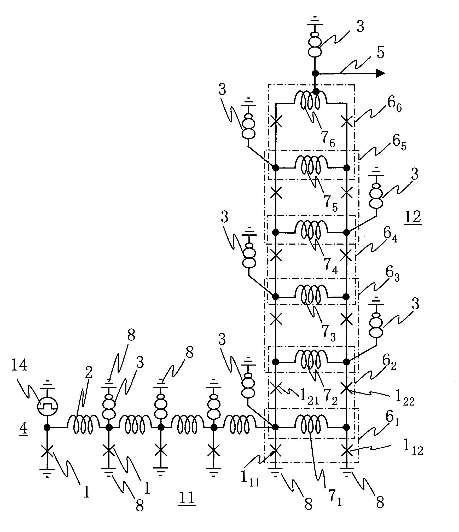
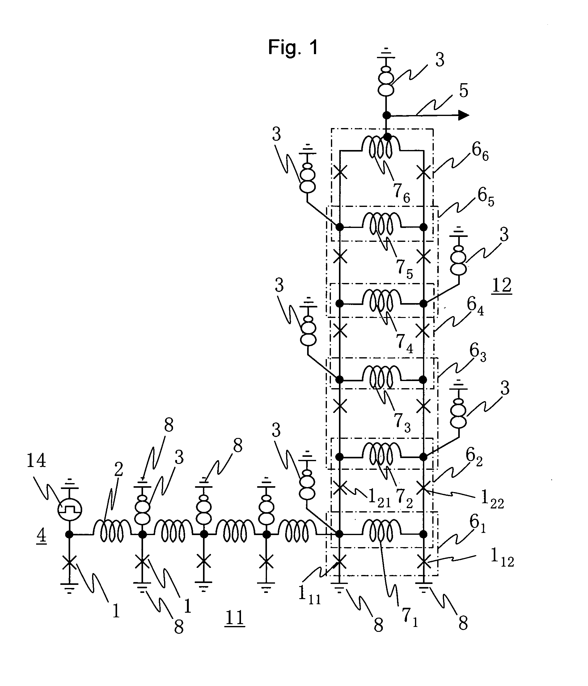
[0038]FIG. 1 shows a superconducting driver circuit of Embodiment 1 with a superconducting junction transmission line as an input signal line. A superconducting driver circuit 12 has SQUIDs 61, 62, . . . , 66 stacked in six stages. Each of the SQUIDs 6 has superconducting junctions 1 on the right and left sides and inductors 7 on the upper and lower sides. The SQUID 61 in the lowermost stage has a loop having an inductor 71 and two superconducting junctions 111 and 112. The SQUID 62 in the second stage to the SQUID 66 in the uppermost stage each have a loop construction sharing the upper and lower SQUIDs and the inductors 7. For instance, the SQUID 62 has a loop having two inductors 71 and 72 and two superconducting junctions 121 and 122. The values of critical currents of the superconducting junctions are lower from the SQUID in the lower stage toward the SQUID in the upper stage. Specifically, in FIG. 1, the critical current values of the superconducting junctions 1 are 0.25 mA in...

embodiment ii

[0057]FIG. 7 shows a superconducting driver circuit of Embodiment 2 with a superconducting junction transmission line as an input signal line. A superconducting driver circuit 13 has SQUIDs 621, 622, . . . , 624 are stacked in four stages. As is understood from the comparison with FIG. 1, the superconducting driver circuit of Embodiment 2 has one SQUID 624 in the uppermost stage, two SQUIDs 623 in the next stage, three SQUIDs 622 in the stage after next, and four SQUIDs 621 in the lowermost stage are connected in parallel, respectively. An inductor 7 is shared between the upper and lower SQUIDs. The adjacent SQUIDs connected in parallel share a superconducting junction.

[0058]The critical currents of the superconducting junctions 1 constructing the SQUIDs are all values almost equal to each other. The values of the sums of the critical currents of the superconducting junctions in the respective stages are lower from the SQUID in the lower stage toward the SQUID in the upper stage. Th...

embodiment iii

[0065]FIG. 10 is a block diagram showing a constructional example of a superconducting circuit in which the superconducting driver circuit according to the present invention is coupled to a superconducting flux quantum circuit. The entire superconducting circuit has a superconducting flux quantum circuit 101, a superconducting flux quantum-voltage converter circuit 102, and a superconducting driver circuit 103. These circuits are connected by superconducting junction transmission lines 11. The superconducting flux quantum circuit 101 is a circuit performing various kinds of logic processing using a flux quantum as a signal. The superconducting driver circuit 103 is the above-described circuit as Embodiment 1 or 2.

[0066]FIG. 11 shows a circuit example of the superconducting flux quantum-voltage converter circuit. The superconducting flux quantum-voltage converter circuit is a circuit which continuously generates a flux quantum train as an output 5 for each reaching of a flux quantum ...


PUM


Abstract

To obtain a superconducting driver circuit which can obtain an output voltage of several millvolts or above, can use a DC power source as a driving power source, can form no capacitance between it and a ground plane, and has a small occupation area, the superconducting driver circuit is constructed by superconducting flux quantum interference devices (SQUIDs) each constructing a closed loop having as components two superconducting junctions and an inductor. The SQUIDs share the inductors and are connected in series in three or more stages.

Description

BACKGROUND OF THE INVENTION[0001]The present invention relates to the superconducting electronics field. More specifically, the present invention relates to a superconducting driver circuit of a superconducting flux quantum circuit which uses a flux quantum permitting high-speed signal processing as the carrier of a signal and is used for a measuring circuit for high-speed signal observation, an analog-to-digital signal converter circuit for high-speed analog signal processing, or a high-speed digital data processing circuit.[0002]Two types of prior art driver circuits which are used for the output part of a superconducting flux quantum circuit and have a signal voltage amplifying function are considered and are used in a superconducting circuit. The prior art and embodiments will be described below with reference to the drawings. Only when discriminating between the parts indicated by the reference numerals, numerical subscripts will be identified as needed.[0003]FIG. 2 is a diagra...

Claims


Application Information

Patent Timeline
Patent Type & Authority Patents(United States)
IPC IPC(8): G01R33/02H01L39/22H03F19/00H03K17/92H03K19/195
CPCH03K19/1954Y10S505/846
Inventor TARUTANI, YOSHINOBUHORIBE, MASAHIROTANABE, KEIICHI
Owner INT SUPERCONDUCTIVITY TECH CENT
Why Eureka
Try Eureka