Superconducting driver circuit
- Summary
- Abstract
- Description
- Claims
- Application Information
AI Technical Summary
Benefits of technology
Problems solved by technology
Method used
Image
Examples
embodiment i
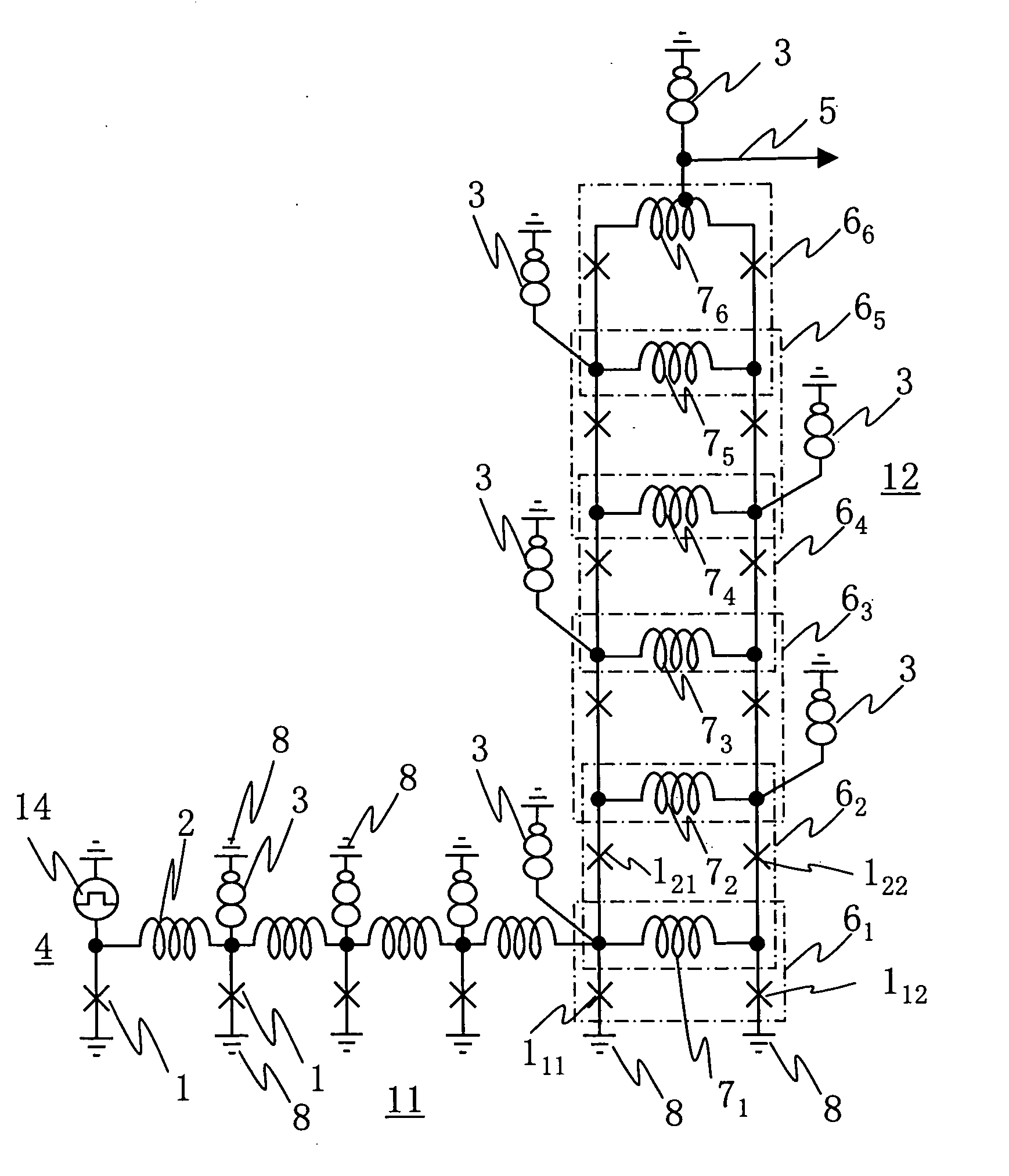
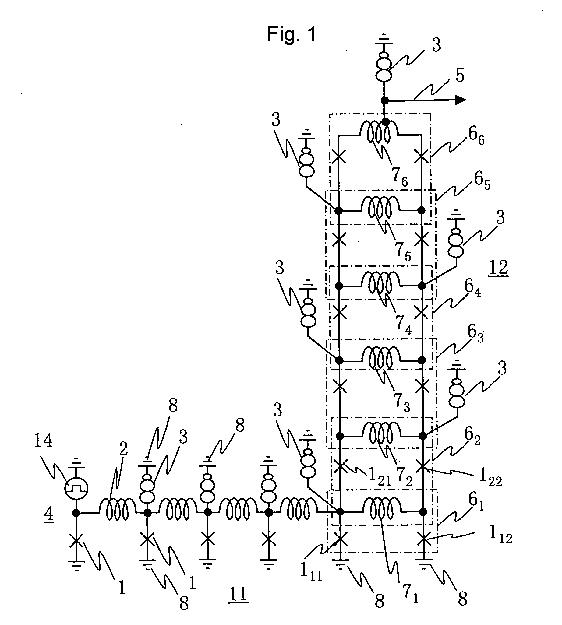
[0038]FIG. 1 shows a superconducting driver circuit of Embodiment 1 with a superconducting junction transmission line as an input signal line. A superconducting driver circuit 12 has SQUIDs 61, 62, . . . , 66 stacked in six stages. Each of the SQUIDs 6 has superconducting junctions 1 on the right and left sides and inductors 7 on the upper and lower sides. The SQUID 61 in the lowermost stage has a loop having an inductor 71 and two superconducting junctions 111 and 112. The SQUID 62 in the second stage to the SQUID 66 in the uppermost stage each have a loop construction sharing the upper and lower SQUIDs and the inductors 7. For instance, the SQUID 62 has a loop having two inductors 71 and 72 and two superconducting junctions 121 and 122. The values of critical currents of the superconducting junctions are lower from the SQUID in the lower stage toward the SQUID in the upper stage. Specifically, in FIG. 1, the critical current values of the superconducting junctions 1 are 0.25 mA in...
embodiment ii
[0057]FIG. 7 shows a superconducting driver circuit of Embodiment 2 with a superconducting junction transmission line as an input signal line. A superconducting driver circuit 13 has SQUIDs 621, 622, . . . , 624 are stacked in four stages. As is understood from the comparison with FIG. 1, the superconducting driver circuit of Embodiment 2 has one SQUID 624 in the uppermost stage, two SQUIDs 623 in the next stage, three SQUIDs 622 in the stage after next, and four SQUIDs 621 in the lowermost stage are connected in parallel, respectively. An inductor 7 is shared between the upper and lower SQUIDs. The adjacent SQUIDs connected in parallel share a superconducting junction.
[0058] The critical currents of the superconducting junctions 1 constructing the SQUIDs are all values almost equal to each other. The values of the sums of the critical currents of the superconducting junctions in the respective stages are lower from the SQUID in the lower stage toward the SQUID in the upper stage. ...
embodiment iii
[0065]FIG. 10 is a block diagram showing a constructional example of a superconducting circuit in which the superconducting driver circuit according to the present invention is coupled to a superconducting flux quantum circuit. The entire superconducting circuit has a superconducting flux quantum circuit 101, a superconducting flux quantum-voltage converter circuit 102, and a superconducting driver circuit 103. These circuits are connected by superconducting junction transmission lines 11. The superconducting flux quantum circuit 101 is a circuit performing various kinds of logic processing using a flux quantum as a signal. The superconducting driver circuit 103 is the above-described circuit as Embodiment 1 or 2.
[0066]FIG. 11 shows a circuit example of the superconducting flux quantum-voltage converter circuit. The superconducting flux quantum-voltage converter circuit is a circuit which continuously generates a flux quantum train as an output 5 for each reaching of a flux quantum...
PUM
 Abstract
Description
Claims
Application Information
 - R&D
- Intellectual Property
- Life Sciences
- Materials
- Tech Scout
- Unparalleled Data Quality
- Higher Quality Content
- 60% Fewer Hallucinations
Browse by: Latest US Patents, China's latest patents, Technical Efficacy Thesaurus, Application Domain, Technology Topic, Popular Technical Reports.
© 2025 PatSnap. All rights reserved.Legal|Privacy policy|Modern Slavery Act Transparency Statement|Sitemap|About US| Contact US: help@patsnap.com


