Systems and methods for determining depth using shuttered light pulses

a technology of shuttered light pulse and depth measurement, which is applied in the direction of distance measurement, cathode-ray oscilloscope, instruments, etc., can solve the problems of insufficient calibration of sensors by existing slp techniques, inability to accurately calculate scene depth, and inability to accurately manipulate above-mentioned measurements

Active Publication Date: 2006-08-22
HONDA MOTOR CO LTD
View PDF9 Cites 44 Cited by
  • Summary
  • Abstract
  • Description
  • Claims
  • Application Information

AI Technical Summary

Problems solved by technology

Existing SLP techniques do not adequately calibrate sensors and manipulate the above-mentioned measurements, especially when more than two shutter locations are used.
As a result, the calculated scene depth is often incorrect.

Method used


Image

  • Systems and methods for determining depth using shuttered light pulses
  • Systems and methods for determining depth using shuttered light pulses
  • Systems and methods for determining depth using shuttered light pulses

Examples


Embodiment Construction

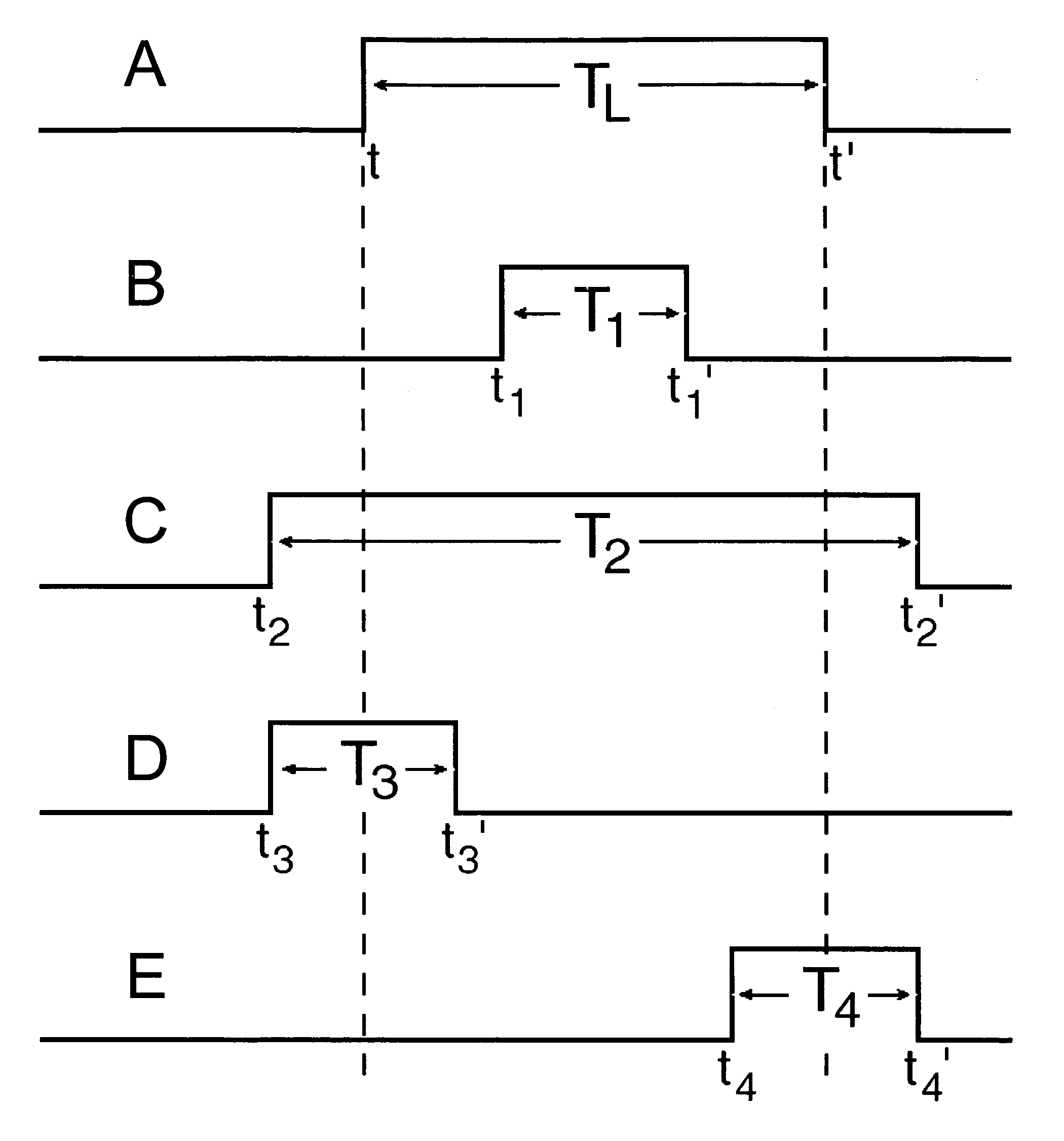
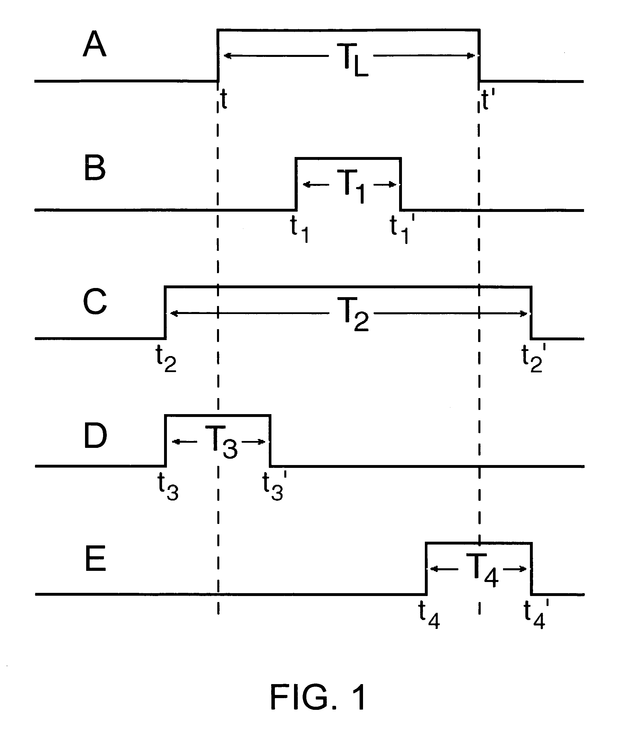
[0019]In the following description, for purposes of explanation, numerous specific details are set forth in order to provide a thorough understanding of the invention. It will be apparent, however, to one skilled in the art that the invention can be practiced without these specific details. In other instances, structures and devices are shown in block diagram form in order to avoid obscuring the invention.

[0020]Reference in the specification to “one embodiment” or “an embodiment” means that a particular feature, structure, or characteristic described in connection with the embodiment is included in at least one embodiment of the invention. The appearances of the phrase “in one embodiment” in various places in the specification are not necessarily all referring to the same embodiment.

[0021]Some portions of the detailed descriptions that follow are presented in terms of algorithms and symbolic representations of operations on data bits within a computer memory. These algorithmic descr...


PUM


Abstract

Systems and methods are presented that use light sensors and computing devices to compute the depth of an object using shuttered light pulses. In one embodiment, depth is determined as follows: A light emitter emits a pulse of light that is directed toward an object. The pulse is reflected off the object and travels toward a beam splitter. The beam splitter splits the reflected pulse into multiple pulses, with each pulse directed to a shuttered sensor with a different shutter location. The shuttered sensors measure the integrated intensity of the light, and these values are used to determine the depth of the object. A method is presented which calibrates a system that has an arbitrary number of shutters and enables the system to determine the depth of an object, even in the presence of ambient illumination and scattered light.

Description

CROSS-REFERENCE TO RELATED APPLICATION[0001]This application claims priority from the following U.S. provisional patent application, which is hereby incorporated by reference: Ser. No. 60 / 510,198, filed on Oct. 9, 2003, entitled “Enhanced Shape Recovery with Shuttered Pulses of Light.”BACKGROUND OF THE INVENTION[0002]1. Field of the Invention[0003]The present invention relates to using light sensors and computing devices to compute the depth of a scene. More particularly, the present invention relates to using light sensors and computing devices to compute the depth of a scene using shuttered light pulses.[0004]2. Description of Background Art[0005]The fields of optical range finding and optical range imaging are concerned with using light to determine the depth of a scene. Approaches that use light to determine the depth of a scene include interferometry, triangulation, phase shift measurement, and time-of-flight measurement. Interferometry techniques calculate the interference pat...

Claims


Application Information

Patent Timeline
Patent Type & Authority Patents(United States)
IPC IPC(8): G01C3/00G04D7/00G01C3/08G01S17/10G01S17/18G01S17/894G02B7/32G03B13/00G03B13/36G03B15/02G06F
CPCG01C3/08G01S17/10G03B13/36G01S17/89G02B7/32G01S17/107G01S17/18G01S17/894
Inventor GONZALEZ-BANOS, HECTOR H.DAVIS, JAMES E.
Owner HONDA MOTOR CO LTD
Why Eureka
Try Eureka