Disk drive employing momentum based unload during power failure

a technology of power failure and disk drive, applied in the field of disk drives, can solve the problems of increasing the overall cost of the disk drive, inefficient power use, and efficient (expensive) vcm

Active Publication Date: 2006-08-22
WESTERN DIGITAL TECH INC
View PDF8 Cites 114 Cited by
  • Summary
  • Abstract
  • Description
  • Claims
  • Application Information

AI Technical Summary

Problems solved by technology

Moving the head 2 to the inner diameter of the disk 6 and then to the outer diameter of the disk 6 to ensure the actuator arm 4 reaches the desired velocity results in an inefficient use of power since it is not necessary for the actuator arm 4 to traverse its entire stroke to attain the desired velocity.
This increases the overall cost of the disk drive as it requires a more efficient (expensive) VCM to ensure the unload operation finishes before the BEMF voltage generated by the spindle motor dissipates.

Method used


Image

  • Disk drive employing momentum based unload during power failure
  • Disk drive employing momentum based unload during power failure
  • Disk drive employing momentum based unload during power failure

Examples


Embodiment Construction

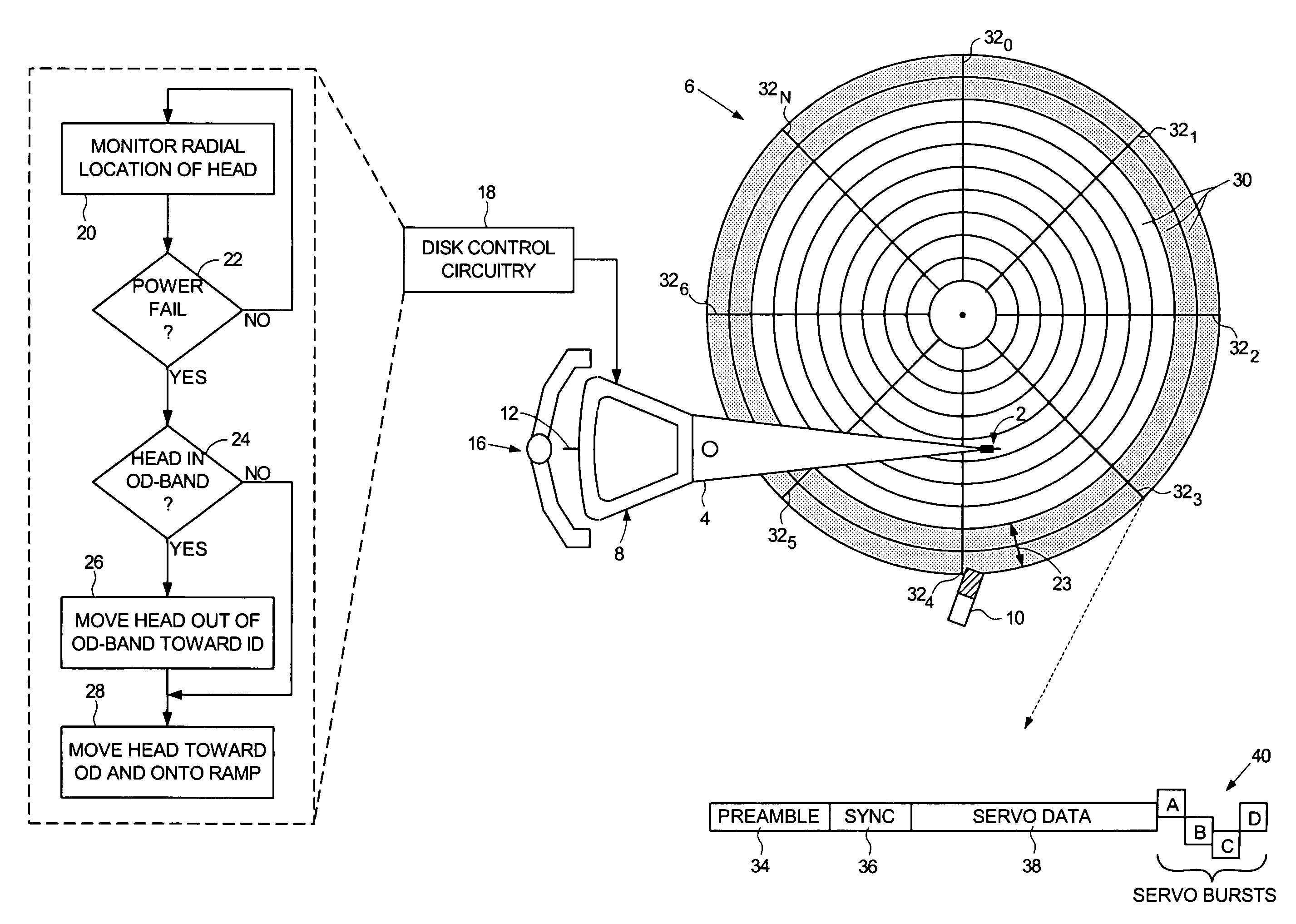
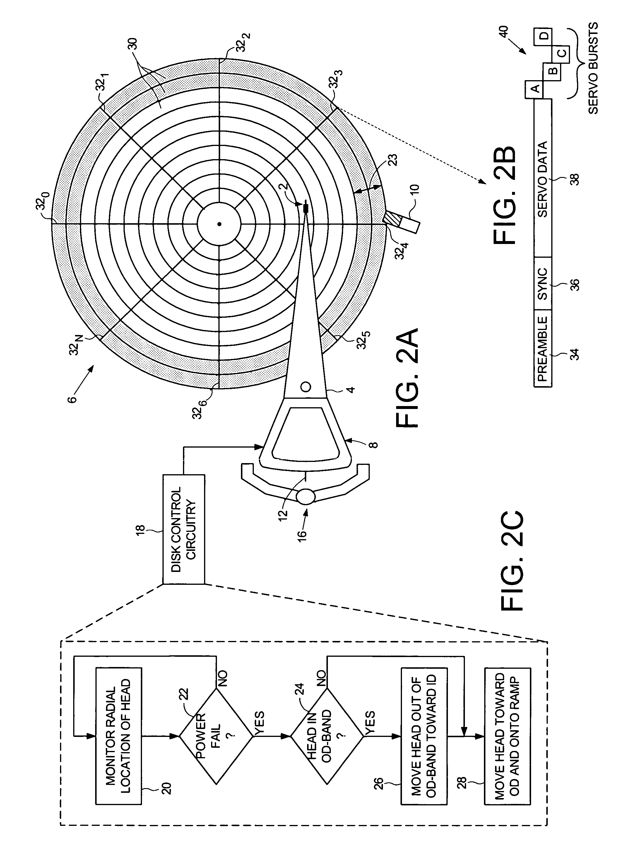
[0019]FIG. 2A shows a disk drive according to an embodiment of the present invention comprising a disk 6, an actuator arm 4, a head 2 connected to a distal end of the actuator arm 4, a voice coil motor (VCM) for rotating the actuator arm 4 about a pivot to actuate the head 2 radially over the disk 6, and a ramp 10 positioned near an outer diameter of the disk 6. During a power failure, disk control circuitry 18 executes an unload operation (FIG. 2C) to unload the actuator arm 4 onto the ramp 10. At step 20 of FIG. 2C, the disk control circuitry 18 monitors the radial location of the head 6. If a power failure is detected at step 22, and the radial location of the head 2 is greater than a predetermined distance 23 from the outer diameter of the disk 6 at step 24 when the power failure occurs, the VCM is controlled at step 28 to move the head 2 toward the outer diameter of the disk 6 until the actuator arm 4 unloads onto the ramp 10. If the radial location of the head 2 is less than t...


PUM

PropertyMeasurementUnit
ODaaaaaaaaaa
outer diameteraaaaaaaaaa
poweraaaaaaaaaa

Abstract

A disk drive is discloses comprising a disk, a head connected to a distal end of an actuator arm, and a voice coil motor (VCM) for rotating the actuator arm about a pivot in order to actuate the head radially over the disk. If when a power failure occurs the radial location of the head is less than a predetermined distance from the outer diameter of the disk, the VCM is controlled to move the head toward the inner diameter of the disk and stopping the head before it reaches the inner diameter of the disk. The VCM is then controlled to move the head toward the outer diameter of the disk until the actuator arm unloads onto a ramp.

Description

BACKGROUND OF THE INVENTION[0001]1. Field of the Invention[0002]The present invention relates to disk drives. More particularly, the present invention relates to a disk drive employing momentum based unload during power failure.[0003]2. Description of the Prior Art[0004]FIG. 1A shows a prior art disk drive comprising a head 2 connected to a distal end of an actuator arm 4 which is rotated about a pivot by a voice coil motor (VCM) in order to actuate the head 2 radially over a disk 6. The VCM comprises a voice coil 8 that generates a magnetic flux when energized with current. The magnetic flux generated by the voice coil 8 interacts with magnetic flux generated by permanent magnets (not shown) to generate a torque that rotates the actuator arm about the pivot.[0005]A spindle motor (not shown) rotates the disk 6 while the head 2 accesses a target data track on the disk 6. During a power failure, the head 2 is parked using the back EMF (BEMF) voltage present over the spindle motor wind...

Claims


Application Information

Patent Timeline
Patent Type & Authority Patents(United States)
IPC IPC(8): G11B21/02
CPCG11B21/12
Inventor RYAN, ROBERT P.DESAI, ASHOK K.MELKOTE, HEMANTCHEN, JENGHUNGAGNESS, JOHN R.DAWSON, TERRY C.
Owner WESTERN DIGITAL TECH INC
Why Eureka
Try Eureka