Distributed static var compensation (DSVC) system for wind and water turbine applications

a wind and water turbine and static var compensation technology, applied in the direction of flexible ac transmission, electrical apparatus, ac network circuit arrangement, etc., can solve the problems of increasing the cost of the generator, increasing the cost of the solid-state power electronics, and becoming a capital expense, so as to improve the overall control of the wind turbine and reduce the distance between the turbine and the associated reactive compensation network. , the effect of easy adaptability

Inactive Publication Date: 2006-08-22
UNITED TECH CORP
View PDF6 Cites 85 Cited by
  • Summary
  • Abstract
  • Description
  • Claims
  • Application Information

AI Technical Summary

Benefits of technology

The invention uses small groups of switches called SCR switched power factor capacitors connected to a central monitoring station to quickly adjust the electricity supplied from the grid to wind or water turbines. This helps achieve faster and more accurate control over the voltage and power factors needed for optimal performance. By dividing the switching equipment into smaller units, it can be adapted to different types of turbines with ease. Additionally, placing this distribution system close to each individual turbine reduces the impact on other parts of the electrical infrastructure and provides better accuracy in controlling the final voltage levels generated by the turbines.

Problems solved by technology

The technical problem addressed in this patent text is how to quickly and accurately control the voltage or power factors of utilization lines connected to wind or tidal turbines, especially when the generators operates at a power factor of unity or lower. Existing solutions such as static var compensators, synchronous conditioners, contacts, and statistical models all come with limitations including slow response times, high costs, and inflexible design. There is also a desire for a modular control system that can adjust to different types, sizes, and configurations of wind or water turbines.

Method used


Image

  • Distributed static var compensation (DSVC) system for wind and water turbine applications
  • Distributed static var compensation (DSVC) system for wind and water turbine applications
  • Distributed static var compensation (DSVC) system for wind and water turbine applications

Examples


Embodiment Construction

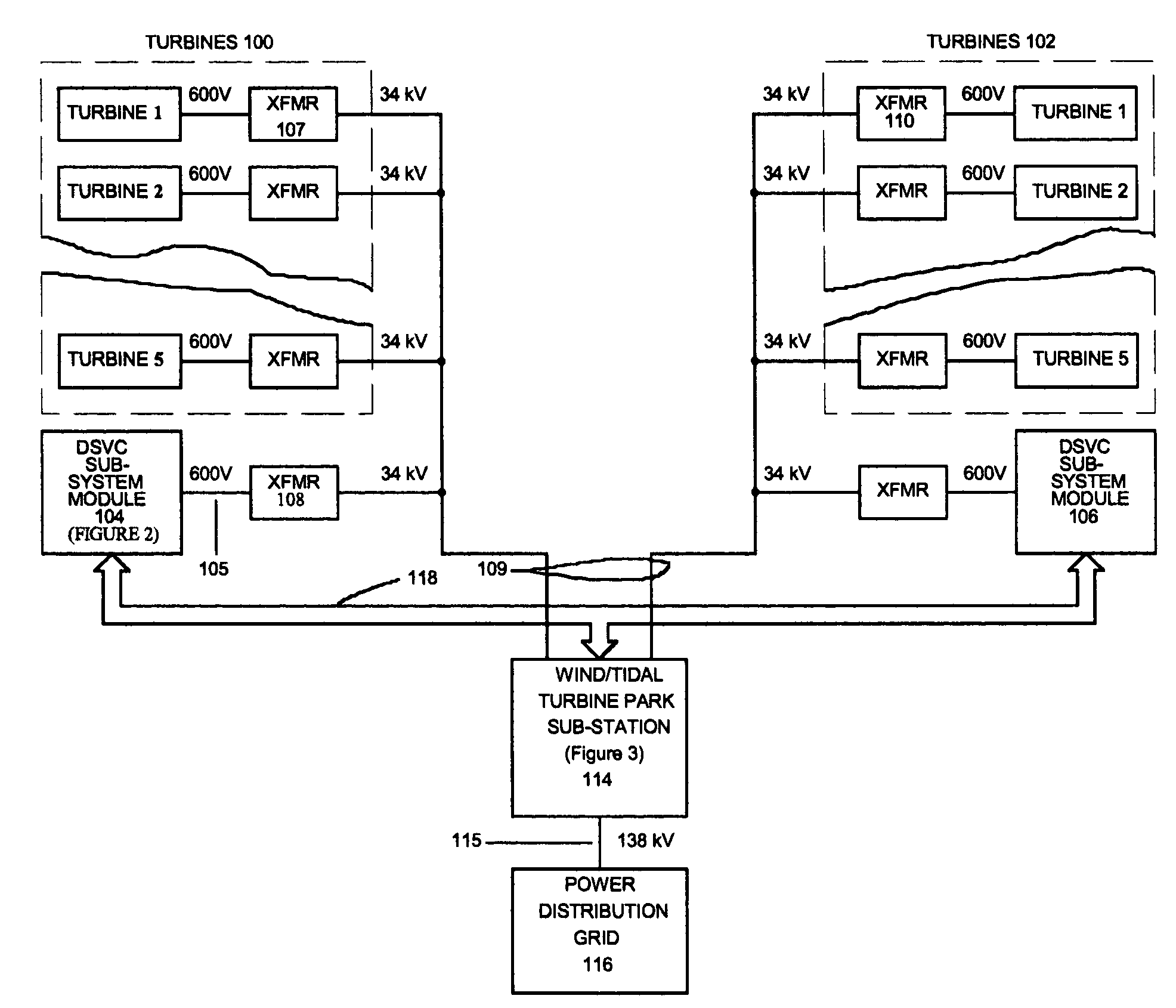
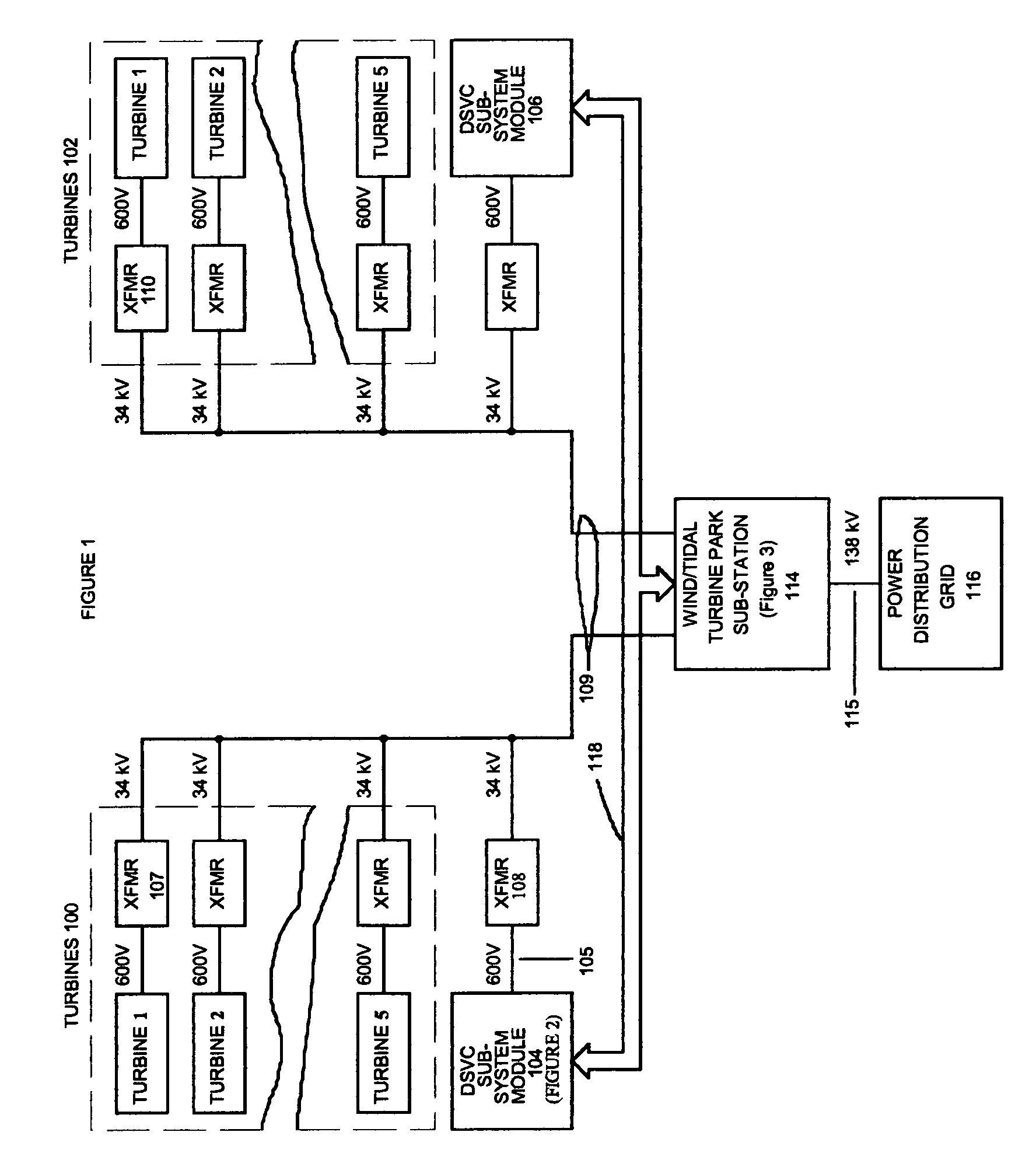
[0037]Refer to FIG. 1, which is a block diagram of a system for correcting the reactive component of wind or water generated electrical power in a power generating system in which the invention is embodied. Wind turbines mounted on top of a tower or tidal turbines tethered underwater generate electrical power that varies with fluctuations in wind speed or water current, or the fluid flow of wind or water past the turbine blades. The turbine generators operate at a power factor of unity or less and do not have a method of power factor correction at the generator. Under these conditions there is a drop in the distribution line voltage as the power output of the turbines increases due to increased wind speed or increased water current.

[0038]Within the broken lines of logic blocks 100 and 102 are groups of wind or water turbines connected by their own transformers (XFMRS) through a medium voltage collector system to a wind park sub-station 114. Each group of turbines includes single tur...


PUM


Abstract

A power generating system wherein a variable speed turbine is mounted on top of a tower or tethered underwater. The reactive component of turbine generated electrical power is corrected automatically through electronic switched power-factor capacitor banks that are divided into sub-system modules coupled to a central turbine park sub-station. The sub-system modules are of a fixed size and are easily adaptable to different turbine generator types, sizes and groupings. By employing SCR switched power factor capacitors grouped in sub-system modules of fixed size, coupled to a central turbine park sub-station, the converter allows fast, real time control of the utility interconnected power line voltage or power factor.

Description


Claims


Application Information

Patent Timeline
Owner UNITED TECH CORP
Why Eureka
Try Eureka