Unlock instant, AI-driven research and patent intelligence for your innovation.

Handoff method for a communication system of a train

a technology of communication system and handoff method, which is applied in the direction of network topologies, location information based services, mass transportation vehicles, etc., can solve problems such as delay in switching operation

Active Publication Date: 2006-08-22
NEC CORP
View PDF7 Cites 23 Cited by
  • Summary
  • Abstract
  • Description
  • Claims
  • Application Information

AI Technical Summary

Benefits of technology

The present invention provides a mobile communication system and a communication control method that can easily switch between cells and allow mobile units to continuously conduct communication. The system includes a plurality of fixed radio base stations and a mobile unit with at least two modules of radio devices mounted at positions within the mobile unit. The mobile unit establishes communication networks with the base stations using a radio device connecting module. The communication control unit includes a radio wave control module that compares values of radio waves received by the mobile unit from the base stations and selects the highest value as the radio wave level for the mobile unit. The system also includes a positional information measuring module that measures the central position of the mobile unit and a positional information storage module that stores installation positions of the fixed radio base stations. The communication control unit uses the positional information to retrieve the installation position of the base station and establish communication networks accordingly. The technical effects of the invention include improved communication continuity and efficiency in mobile communication.

Problems solved by technology

This complicates control processing of the switching section and hence there exits a fear of delay in the switching operation to establish a linked state in the mobile communication unit.

Method used


Image

  • Handoff method for a communication system of a train
  • Handoff method for a communication system of a train
  • Handoff method for a communication system of a train

Examples


first embodiment

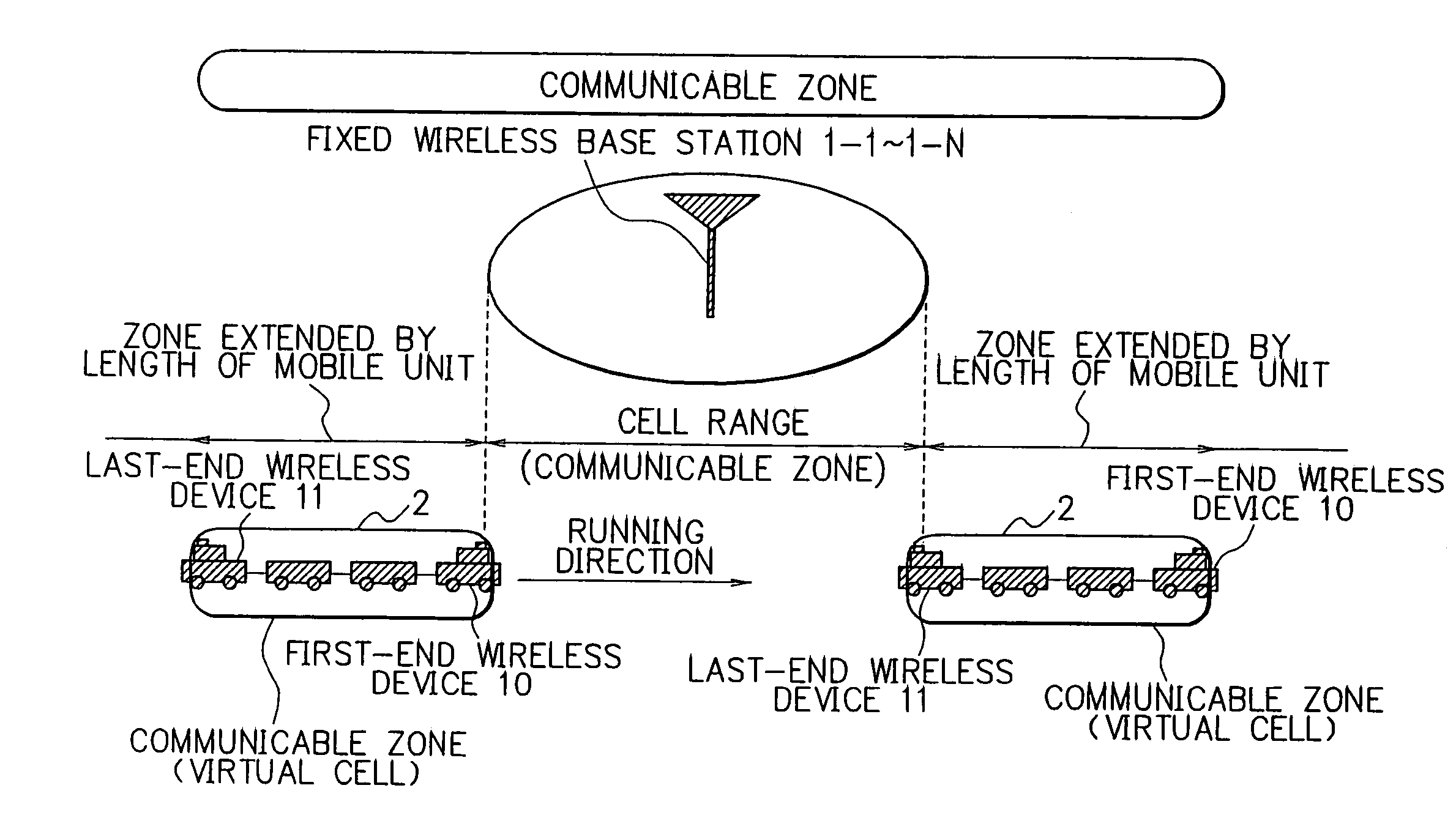
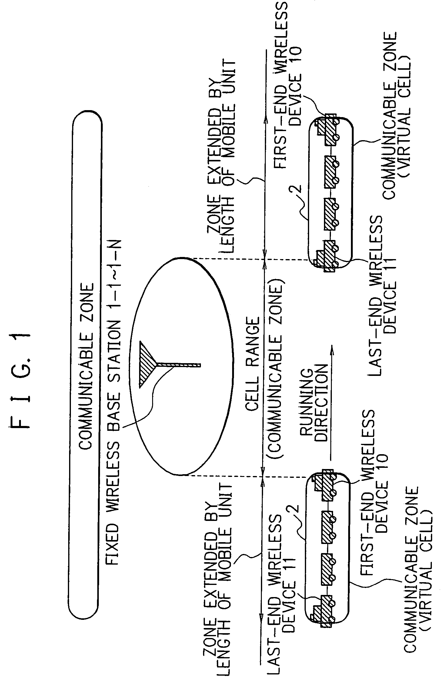
[0049]Description will now be given of a first embodiment of a mobile communication system by referring to FIG. 1.

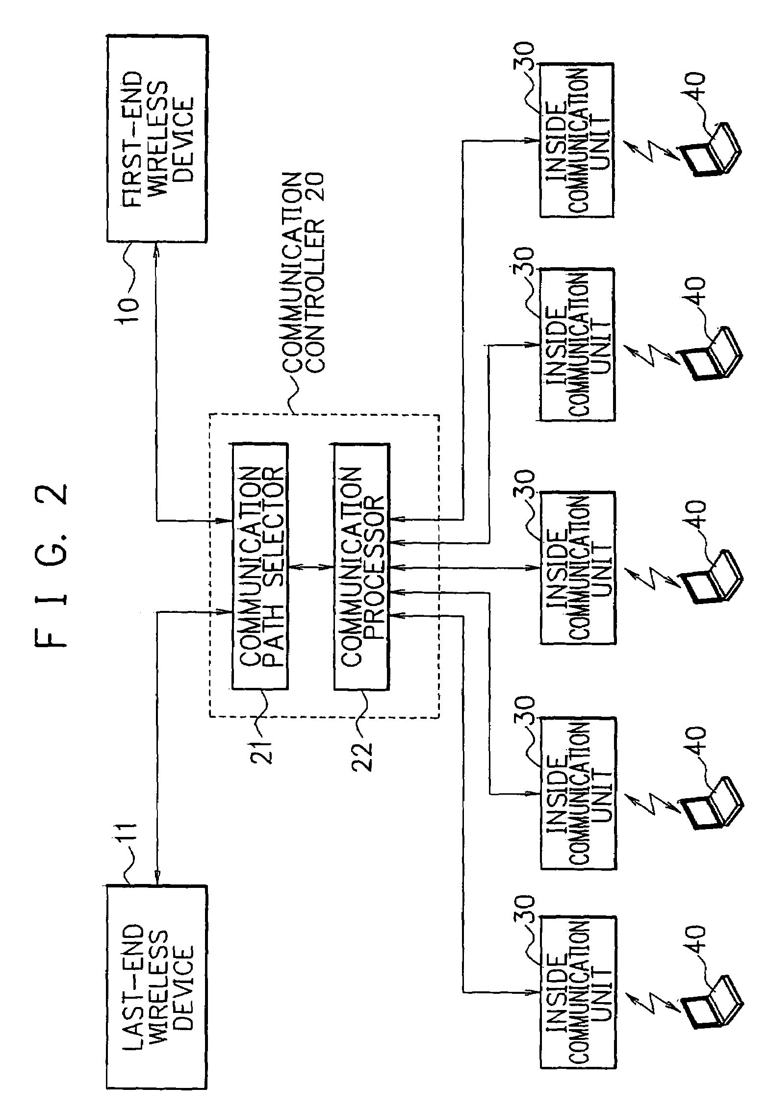
[0050]The system includes fixed radio base stations 1-1 to 1-N (N is an integer more than one) and a mobile unit 2. The unit 2 includes wireless device 10 and 11 to conduct wireless or radio communication with the base stations 1-1 to 1-N.

[0051]The base stations 1-1 to 1-N configure respective cells as ranges of arrival of a particular radio wave and communicate signals with the wireless devices 10 and 11 of the mobile unit 2 existing in such a cell. When the mobile unit 2 moves to a position in a cell configured by one of the base stations 1-1 to 1-N, a link is set between the wireless devices 10 and 11 and the pertinent base station to conduct communication therebetween.

[0052]The mobile unit 2 is, for example, a mobile unit having a predetermined length such as a train and moves between the cells of the base stations 1-1 to 1-N. In the embodiment, a radio device, i.e.,...

second embodiment

[0072]Next, description will be given of a second embodiment in accordance with the present invention.

[0073]The second embodiment differs from the first embodiment as below. In the operation to set the linked state between the radio device 10 and one of the base stations 1-1 to 1-N or that between the radio device 11 and one of the base stations 1-1 to 1-N in the mobile unit 2, a radio wave level received by the device 10 from the base station linked with the device 10 is compared with a radio wave level received by the device 11 from the base station linked therewith. As a result, the system sets the linked state in the mobile unit 2 for the radio device 10 or 11 with a higher radio wave level. Referring next to FIG. 7, description will be given of the second embodiment of a mobile communication system.

[0074]In the second embodiment, the communication controller 20 connected to the first-end and last-end wireless devices 10 and 11 includes a radio wave controller 23 to control the ...

third embodiment

[0077]Next, description will be given of a third embodiment in accordance with the present invention.

[0078]As can be seen from FIG. 8, the third embodiment is implemented by additionally disposing in the first embodiment a positional information measuring section 24 to measure a present position (a central position) of the mobile unit 2 in a moving state thereof, a positional information storing section 25 to store installation positions of fixed radio base stations 1-1 to 1-N (N is an integer more than one), and a positional information retrieving section 26 to retrieve the installation position of one of the base stations 1-1 to 1-N nearest to the mobile unit 2. In the configuration of the mobile communication system, to establish the linked state between the mobile unit 2 and the base station determined to be nearest to the unit 2 by the retrieving section 26, the connection between the first-end radio device 10 and the communication processor 22 or that between the last-end radi...


PUM


Abstract

In a mobile communication system, even when cells formed by fixed radio base stations are separated from each other, the switching operation between the cells is easily carried out to conduct continuous communication. A first-end radio device mounted in a first-end section of a mobile unit and linked with one of fixed radio base stations or a last-end radio device mounted in a last-end section of a mobile unit and linked with one of fixed radio base stations is selected. A communication network is established between the first-end or last-end radio device thus selected and a plurality of mobile terminals in the mobile unit. This makes it possible to construct a communicable zone (a virtual cell) on the mobile unit and hence elongates the ranges of cells formed by the base stations.

Description

BACKGROUND OF THE INVENTION[0001]1. Field of the Invention[0002]The present invention relates to a mobile communication system and a communication control method for use with the system including cells of which each defines a predetermined radio wave arrival range of radio waves from a fixed base station associated with the cell, and in particular, to a mobile communication system and a communication control method for use with the system suitable for a mobile unit or module such as a train moving at a high speed.[0003]2. Description of the Prior Art[0004]To guarantee wide uses of mobile communication terminal devices using radio or wireless communication, communication enterprises have been endeavoring to develop areas for the terminal devices. Recently, the areas have been broaden beyond indoor areas to include zones such as places in a subway train and a tunnel. The terminal device can be used in a moving train and even in a high-speed mobile unit such as a train of the Japanese ...

Claims


Application Information

Patent Timeline
Patent Type & Authority Patents(United States)
IPC IPC(8): H04B1/06H04B1/00H04B7/26H04W4/42H04W16/00H04W84/00H04W88/18
CPCH04W88/18H04W16/00H04W4/04H04W84/00H04W4/42
Inventor YANO, YUKIKO
Owner NEC CORP