Inversion liner and liner components for conduits

a conduit and inversion liner technology, applied in the direction of flexible pipes, pipe elements, mechanical equipment, etc., can solve the problems of less optimized tensile strength, high cost of underground pipe replacement, and often cracks or weakened areas of pipes that need repair, so as to achieve higher modulus and strength, the effect of reducing the thickness of the liner wall

Inactive Publication Date: 2006-08-29
SAINT GOBAIN ADFORS CANADA LTD
View PDF298 Cites 47 Cited by
  • Summary
  • Abstract
  • Description
  • Claims
  • Application Information

AI Technical Summary

Benefits of technology

[0012]The present invention provides inversion liners which, in a first embodiment, include a first flexible fabric layer fastened to a first glass fiber containing layer, a second flexible fabric layer fastened to a second glass fiber containing layer, and a third flexible fabric layer comprising a substantially fluid impermeable layer. These three flexible fabric layers are joined together such that the first and second glass fiber containing layers are sandwiched between the first and second flexible fabric layers, and the third flexible fabric layer is joined to the second flexible fabric layer so that the substantially fluid impermeable layer becomes the outermost layer, and the first flexible fabric layer becomes the innermost layer of the inversion liner, prior to inversion. Following inversion, the resin saturated first flexible fabric layer conforms to the conduit's inner diameter and cures, preferably forming a mechanical lock therewith, while the substantially fluid impermeable layer becomes the liner's inner diameter surface, protecting the conduit and the liner from the corrosive effects of the conduit's contents.
[0014]In still a further embodiment of this invention, a glass-faced liner is provided which includes a first glass fiber containing layer, a first flexible fabric layer fastened to the first glass fiber containing layer, and a second flexible fabric layer disposed over the first flexible fabric layer. A second glass fiber containing layer is disposed over the second flexible fabric layer and fastened thereto, and a third flexible fabric layer is disposed over the second glass fiber containing layer and fastened thereto. This embodiment further includes a fourth flexible fabric layer disposed over the third flexible fabric layer and fastened thereto, and a substantially fluid impermeable layer joined to the fourth flexible fabric layer which becomes the innermost layer of this inversion liner after inversion. This last embodiment is extremely strong, having a flexural modulus of about 700-800 ksi (higher than polyester felt tubes which are about 300 ksi), and can be used for small diameter pipe in layers of less than 15 mm, preferably about 6-12 mm, in thickness, without requiring multiple layers.
[0017]Because of the higher modulus and strength attributable to the glass and fabric building blocks of this invention, a significant reduction in liner wall thicknesses can be achieved, compared to 100% felt liners, while still satisfying the standard design equations of the pipe rehabilitation industry.

Problems solved by technology

Due to cyclical loadings, premature wear, manufacturing defects, corrosion, and other factors, these pipes can often develop cracks or weakened areas requiring repair.
Since the replacement of underground pipes is extremely costly, an alternative is to provide a lining repair while leaving the remaining pipe structure in place.
Needling causes the fibers to generally extend in right angles to the plane of the material, which results in a less optimized tensile strength than if the fibers were oriented in the plane of the material.
The introduction of glass or other high strength fibers in needling operations, while increasing the average tensile strength of the fibers themselves, still presents a less than desirable orientation, since the needled reinforcing fibers are also generally disposed at right angles to the plane of the material.
While this dramatically improves the liner's mechanical properties, this liner has not been recommended for inversion techniques, and was designed for winch-in-place applications.
The Kittson, et al. liner is also difficult to “build”, as in the subsequent building-up of additional liner layers due to the fact that glass layers are not “heat bondable” through conventional means.
Moreover, artisans have generally regarded building up layers of liners within an underground pipe to be impractical.

Method used


Image

  • Inversion liner and liner components for conduits
  • Inversion liner and liner components for conduits
  • Inversion liner and liner components for conduits

Examples


Embodiment Construction

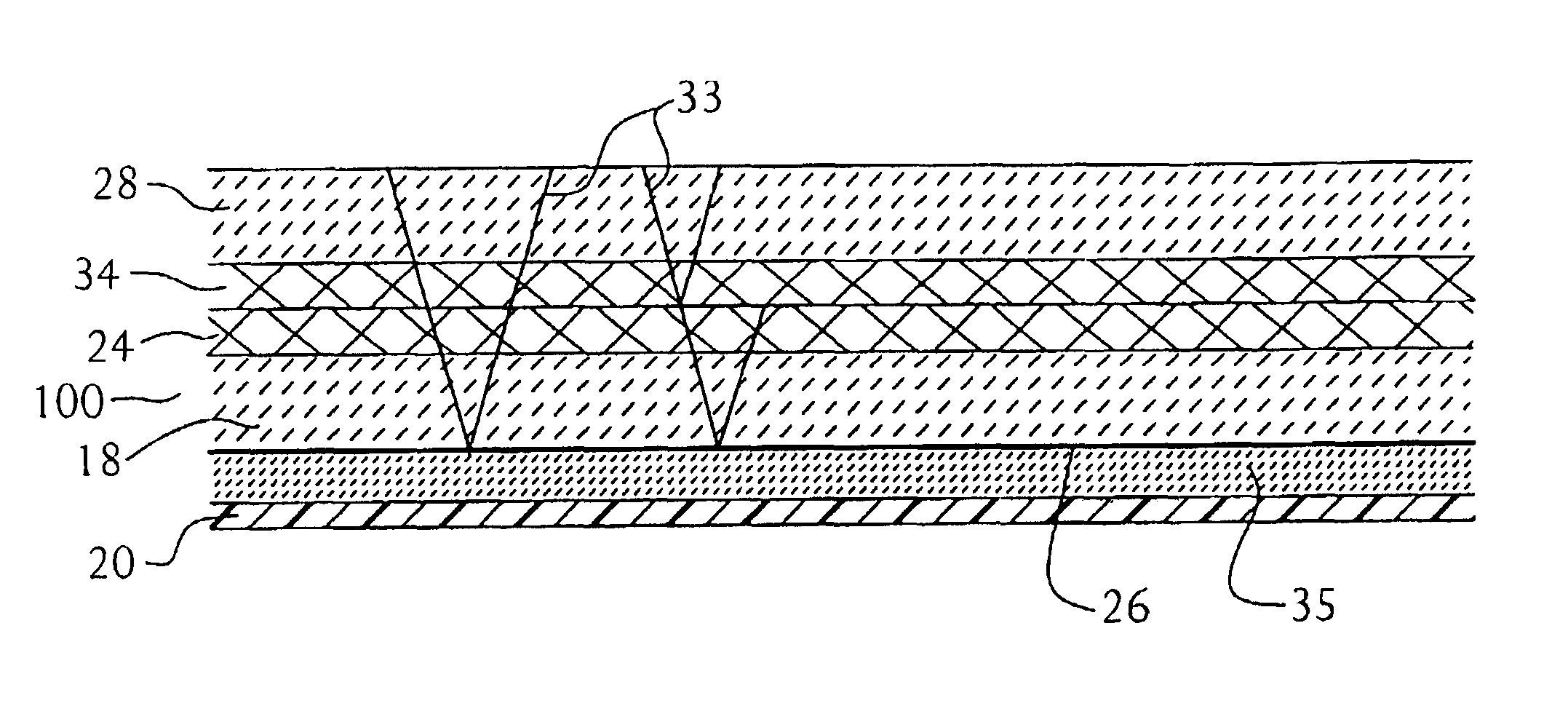
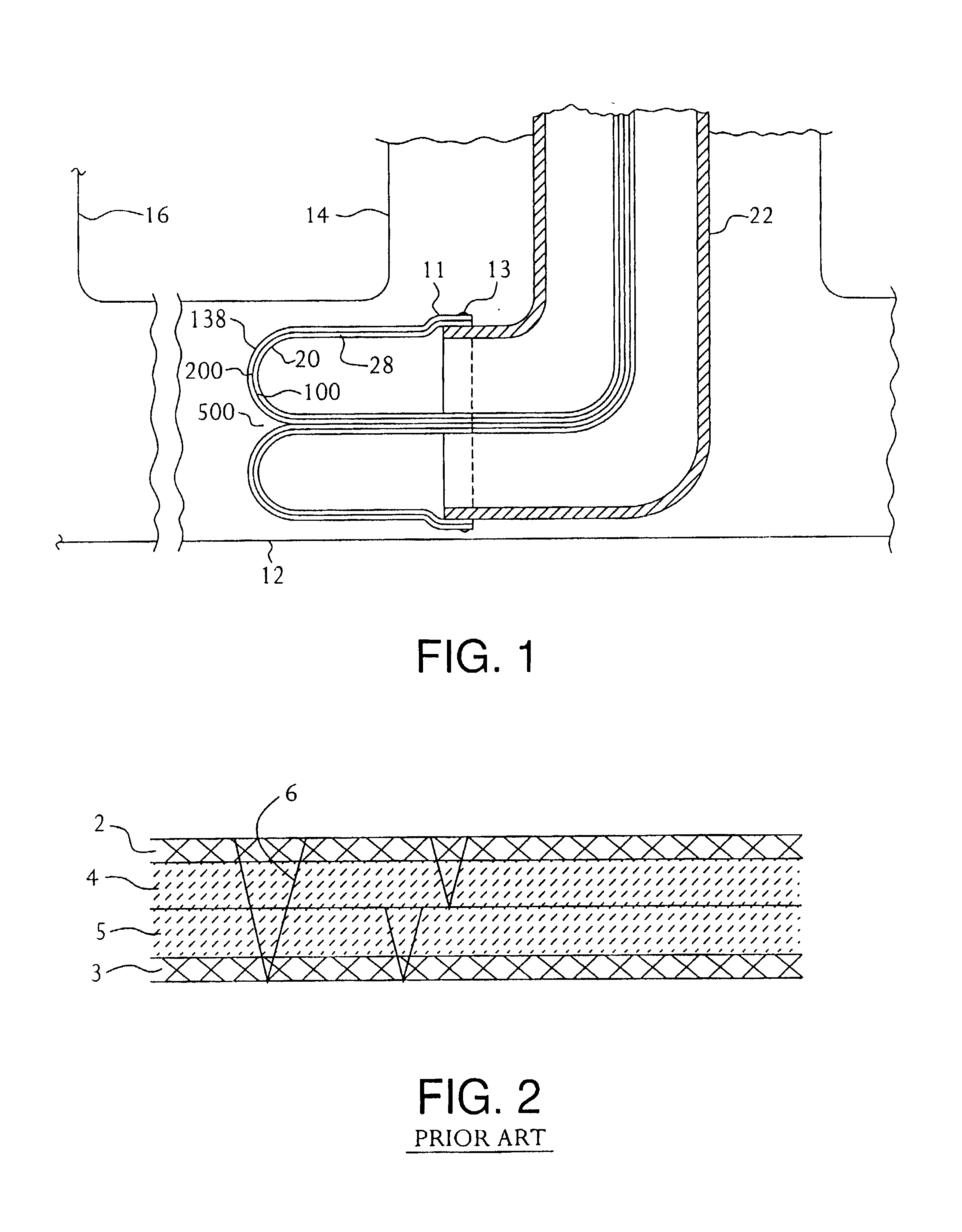
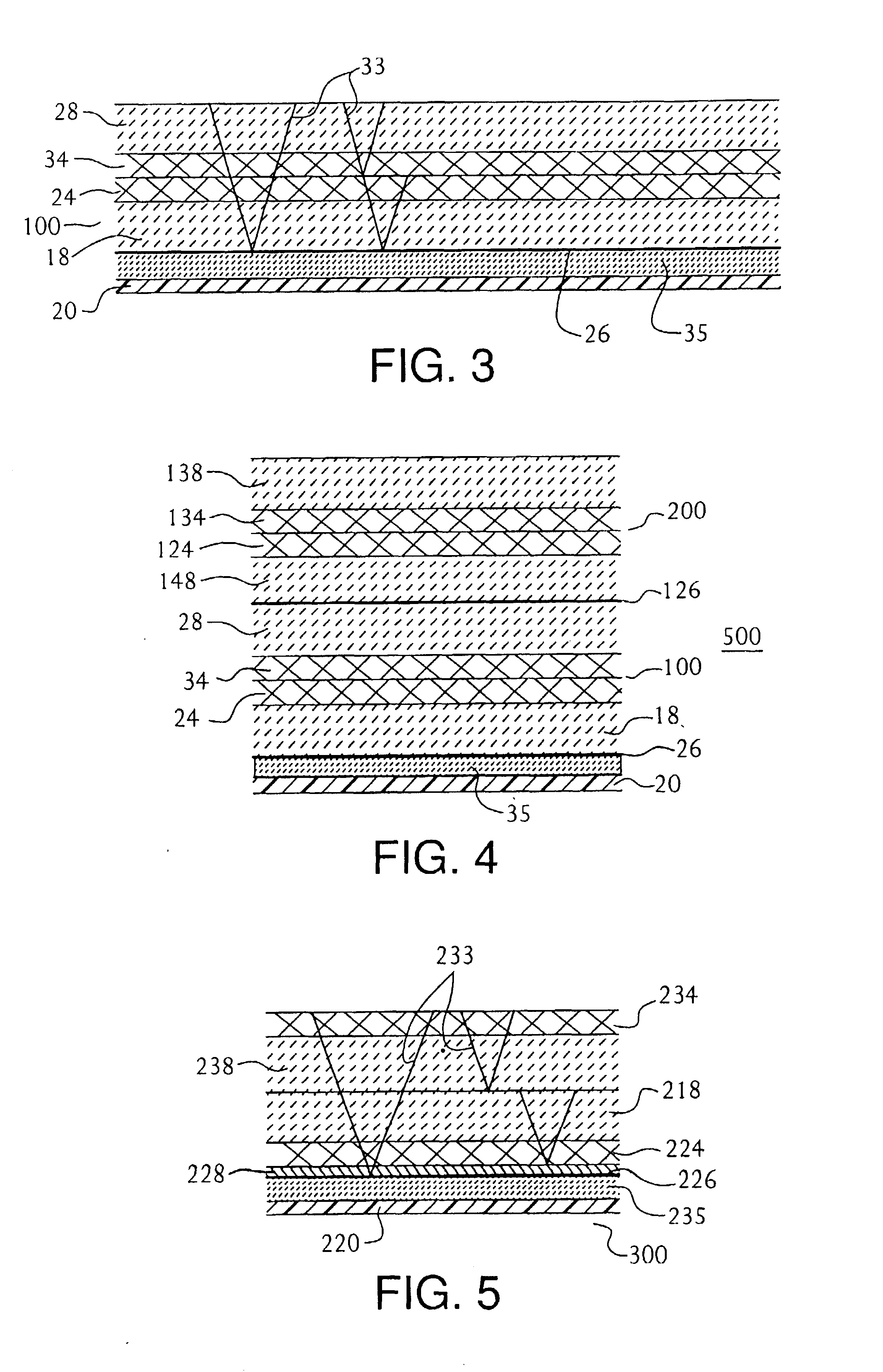
[0025]The present invention is related to inversion liners of the type that can be inverted with the assistance of fluid pressure, such as compressed air, steam or hot water (hereinafter “fluids”) to expand within a defective conduit and generally, mechanically mate or bond within, or come in close proximity to, the inner diameter of the conduit prior to curing to form a substantially corrosion and water resistant sleeve. As such, the liners of this invention are thin, tubular members which can exhibit a tubular, tape-like or ribbon-like cross-section prior to inversion. As used herein, the term “buildable” refers to the ability of the liners of this invention to be adhesively bonded to a second or subsequent liner to build up the thickness of the liner to its final thickness, and the term “glass-faced” means a liner having at least one glass layer located on, or proximate to, its face or faces. Building techniques for liner materials are often useful for large pipes of 36-40 inches...


PUM


Abstract

Inversion liners are provided which in a first embodiment include first and second flexible fabric layers separated by one or more glass fiber containing layers and joined in tubular form. The second flexible fabric layer further is bonded to a third flexible fabric layer comprising a substantially fluid impermeable layer. An invertible glass-faced liner is also provided by this invention which includes a glass facing on one side and a substantially fluid impermeable layer on the other. The substantially fluid impermeable layer is joined to a flexible fabric layer which is preferably heat bonded to a thin veil joined to a second glass containing layer of this liner embodiment. The inversion liners of this invention can be built-up in multiple layers or blocks to meet end-use design demands while still providing flexural moduli in excess of 500 ksi, preferably about 700-800 ksi.

Description

RELATED APPLICATION DATA[0001]This application is related to commonly assigned U.S. Pat. Nos. 5,836,357; 5,931,199; 5,911,246; and 5,873,391 which are all hereby incorporated by reference.FIELD OF THE INVENTION[0002]This invention relates to conduit liners for making repairs in underground piping systems, and more particularly to inversion liners that provide improved strength and greater inversion speed.BACKGROUND OF THE INVENTION[0003]Underground piping systems are essential in providing the transportation of liquids and gases to homes and businesses. Used mostly by utilities in sewer pipes, water pipes, water mains, gas mains, electrical conduits and other applications, such pipes are often found many feet under ground or in inaccessible areas, such as under buildings or roadways.[0004]Due to cyclical loadings, premature wear, manufacturing defects, corrosion, and other factors, these pipes can often develop cracks or weakened areas requiring repair. Since the replacement of unde...

Claims


Application Information

Patent Timeline
Patent Type & Authority Patents(United States)
IPC IPC(8): F16L55/16F16L55/165
CPCF16L55/1656
Inventor WOOLSTENCROFT, JON H.PLEYDON, ROBERTTIGCHELAAR, MARK
Owner SAINT GOBAIN ADFORS CANADA LTD
Why Eureka
Try Eureka