
Balanced mechanical seal assembly

a mechanical seal and assembly technology, applied in the direction of mechanical devices, engine seals, engine components, etc., can solve the problems of limited design of seal faces, double-balanced seals that cannot operate efficiently under reverse pressure conditions, and prior double-balanced mechanical seal assemblies have significant drawbacks, so as to achieve pressure balance and minimize heat generation in the operation of seals

Active Publication Date: 2006-08-29
A W CHESTERTON
View PDF13 Cites 16 Cited by
  • Summary
  • Abstract
  • Description
  • Claims
  • Application Information

AI Technical Summary

Benefits of technology

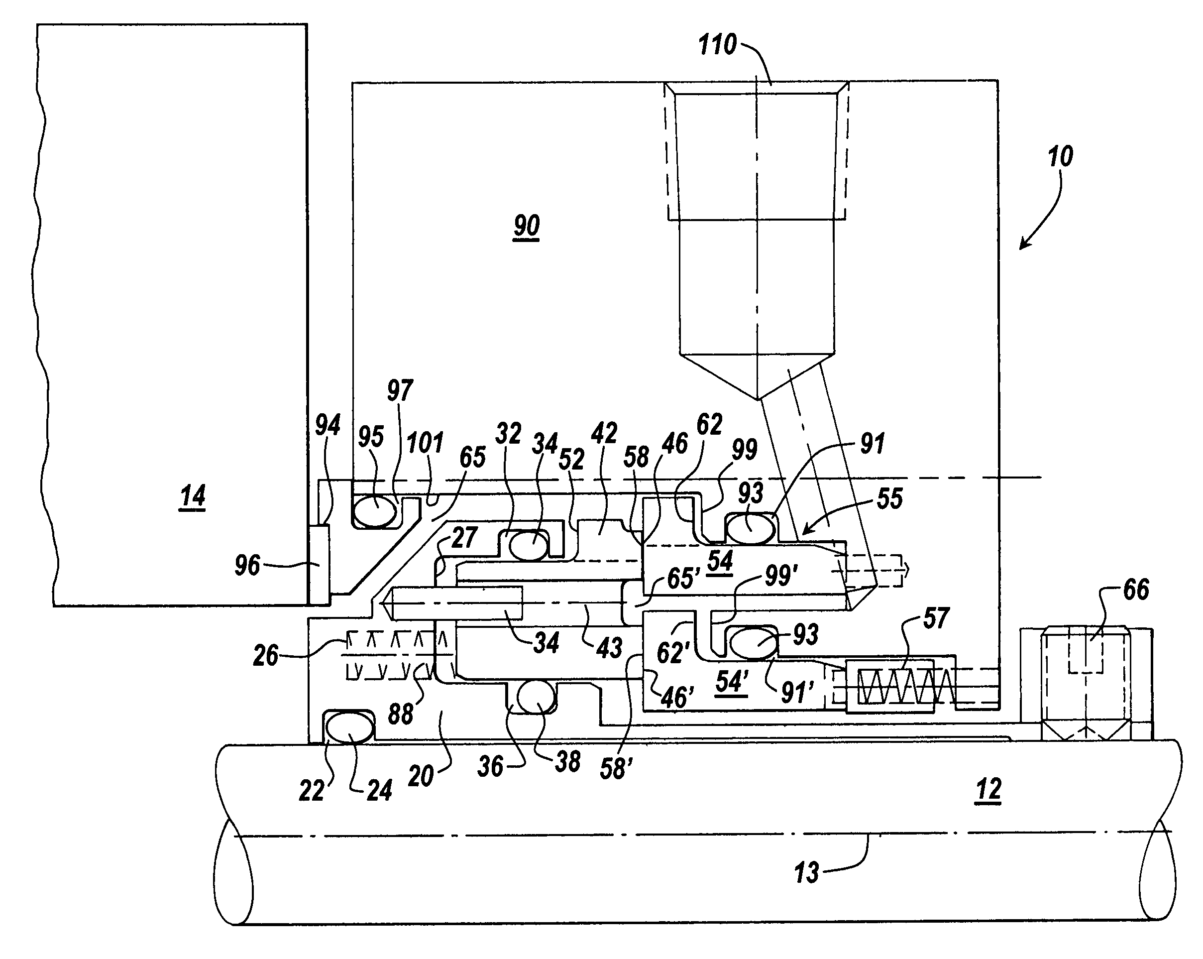
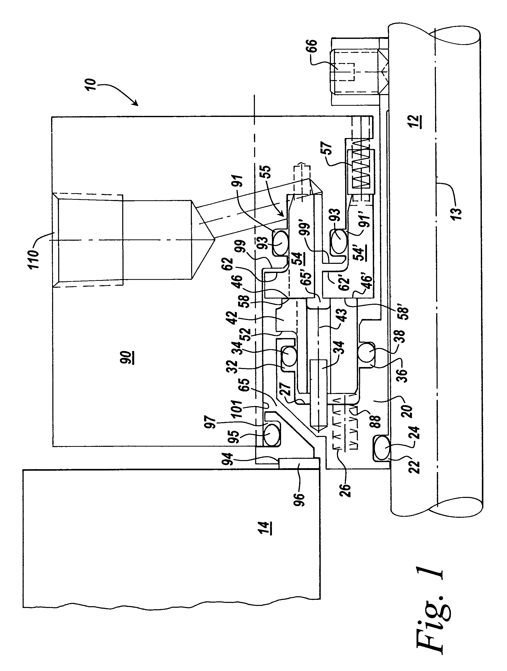
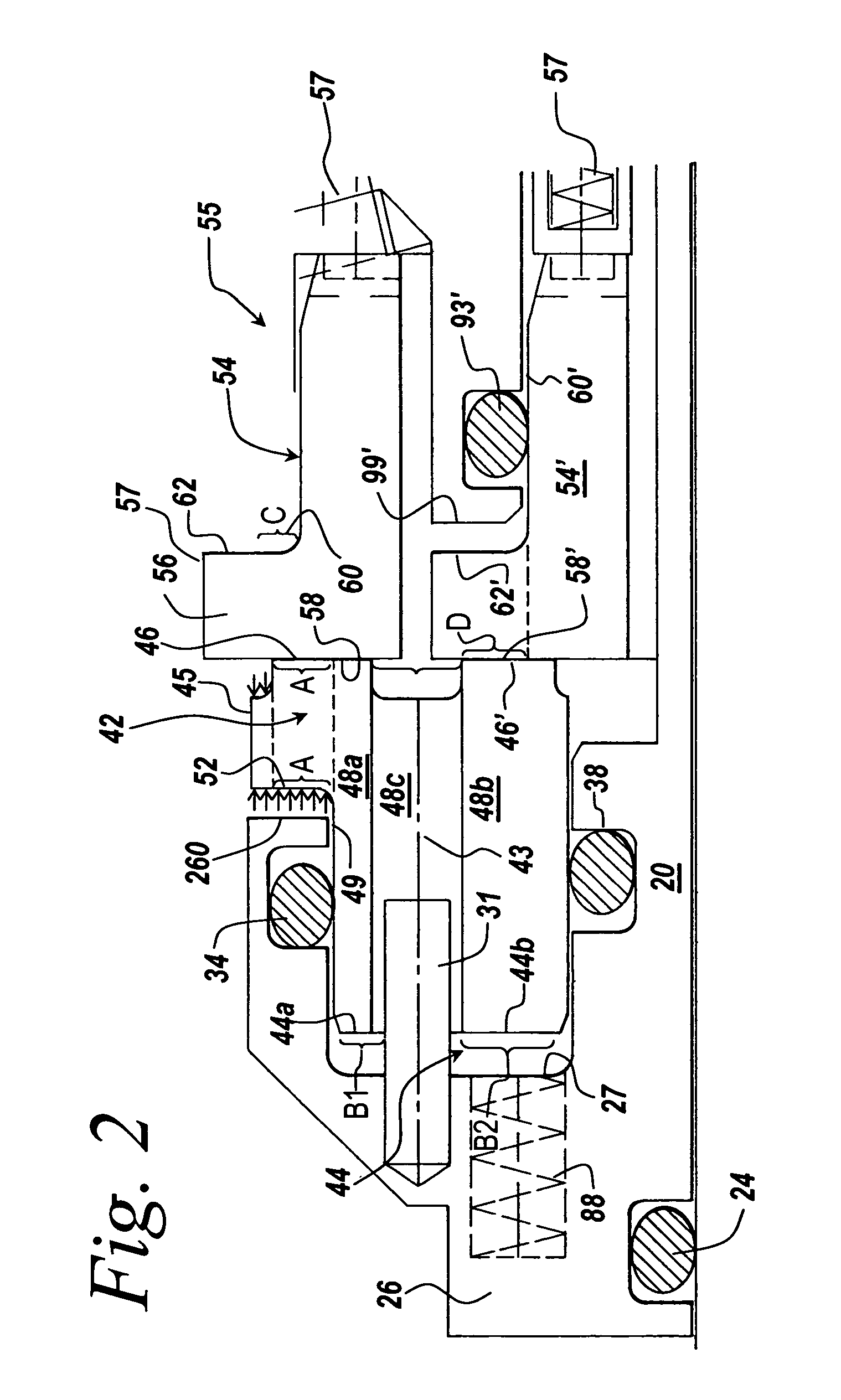
[0010]Under normal operating conditions, when the process fluid pressure is greater than the barrier fluid pressure, the process fluid exerts a force on first piston areas to bias the seal faces together. Under reverse operating conditions, when the barrier fluid pressure is greater than the process fluid pressure, the barrier fluid exerts a force on second piston areas to bias the seal faces together. The combined area of the first piston areas is substantially identical to the combined area of the second piston areas to provide a balanced seal arrangement for standard and reverse pressure conditions without requiring the use of axially movable components.
[0011]Advantageously, a seal according to the present invention achieves pressure balance by virtue of the geometry of the parts, providing fixed, predetermined piston areas on the sides of the rotary and stationary seal members opposite the seal faces without reliance on any movable parts which may be subject to malfunction. An individual piston area is exposed to only one of the fluids. Further, the contact area of the seal faces may be optimized without any limitation imposed by the size of the O-rings defining the balance pressure points. Because it is possible to design seal faces having a small contact area, heat generation in operation of the seal is minimized. Furthermore, the movable interfaces of the mechanical seal do not contact the dirty process fluid and are therefore not subject to additional wear.

Problems solved by technology

Prior double-balanced mechanical seal assemblies have significant drawbacks.
This limits the design of the seal faces for which minimum contact area is desired to reduce heat generation.
An additional drawback of double-balanced mechanical seal assemblies of the prior art is that the double-balanced seal does not operate efficiently under reverse pressure conditions.
Furthermore, the process fluid, which may be dirty and include contaminants, causes dirt and other particles to get caught in the sliding O-ring interface, which causes wear and O-ring hang-up over time, thereby negatively impacting seal performance.

Method used


Image

  • Balanced mechanical seal assembly
  • Balanced mechanical seal assembly
  • Balanced mechanical seal assembly

Examples


Embodiment Construction

[0016]The present invention provides a mechanical seal for mounting to a stationary housing that contains a rotating shaft. The invention will be described below relative to illustrative embodiments. Those skilled in the art will appreciate that the present invention may be implemented in a number of different applications and embodiments and is not specifically limited in its application to the particular embodiment depicted herein.

[0017]The terms “process medium” and “process fluid” used herein generally refer to the medium or fluid being transferred through the housing. In pump applications, for example, the process medium is the fluid being pumped through the pump housing.

[0018]The terms “axial” and “axially” used herein refer to a direction generally parallel to the shaft axis. The terms “radial” and “radially” refer to a direction generally perpendicular to the shaft axis.

[0019]The term “shuttle member” as used herein is intended to include any structure suitable for movement,...


PUM


Abstract

A mechanical seal having a single rotatable seal ring having a pair of concentric seal faces to form a radially inner seal face and a radially outer seal face. The mechanical seal also includes first and second stationary seal rings, each having a seal face, where the seal face of the first stationary seal ring contacts the radially outer seal face of the rotatable seal ring and the seal face of the second stationary seal ring contacts the radially inner seal face of the rotatable seal ring. The seal also includes a sleeve adapted to be mounted about the rotating shaft and rotatably coupled thereto and to the rotatable seal ring, said sleeve having a flange portion that is configured for housing at least a portion of the rotatable seal ring, and a gland for housing at least partially the single rotary seal ring and the first and second stationary seal rings. Under positive and negative pressure conditions, the combined area of the seal piston areas are substantially identical to provide a balanced seal arrangement without requiring the use of axially movable components.

Description

RELATED APPLICATIONS[0001]The present application claims priority to U.S. Provisional Patent Application Ser. No. 60 / 450,795, entitled “Balanced Mechanical Seal Assembly”, filed Feb. 28, 2003, the contents of which are herein incorporated by reference. This application is also related to Ser. No. 10 / 791,514 entitled “Balanced Mechanical Seal Assembly,” filed on even date herewith, the contents of which are herein incorporated by reference.FIELD OF THE INVENTION[0002]The present invention relates to a balanced mechanical seal and more particularly to a double balanced mechanical seal for providing a seal between a rotating shaft and a stationary housing.BACKGROUND OF THE INVENTION[0003]Conventional mechanical seals are employed in a wide variety of mechanical apparatuses to provide a pressure-tight and a fluid-tight seal between a rotating shaft and a stationary housing. The seal is usually positioned about the rotating shaft, which is mounted in and protrudes from the stationary hou...

Claims


Application Information

Patent Timeline
Patent Type & Authority Patents(United States)
IPC IPC(8): F16J15/34
CPCF16J15/3404F16J15/3484F16J15/3448F16J15/3472F16J15/38F16J15/40
Inventor AZIBERT, HENRI V.
Owner A W CHESTERTON
Learn More