Delivery pump for cryogenic fuels

A low-temperature fuel and delivery pump technology, which is applied to the components of pumping devices for elastic fluids, liquid fuel engines, pumps, etc., can solve the problem of not being able to seal 100%, and achieve the effect of optimizing sealing and reducing fuel volume.

Inactive Publication Date: 2019-04-02
ROBERT BOSCH GMBH
View PDF7 Cites 0 Cited by
  • Summary
  • Abstract
  • Description
  • Claims
  • Application Information

AI Technical Summary

Problems solved by technology

However, these seals are also characteri...

Method used


Image

  • Delivery pump for cryogenic fuels
  • Delivery pump for cryogenic fuels

Examples


Embodiment Construction

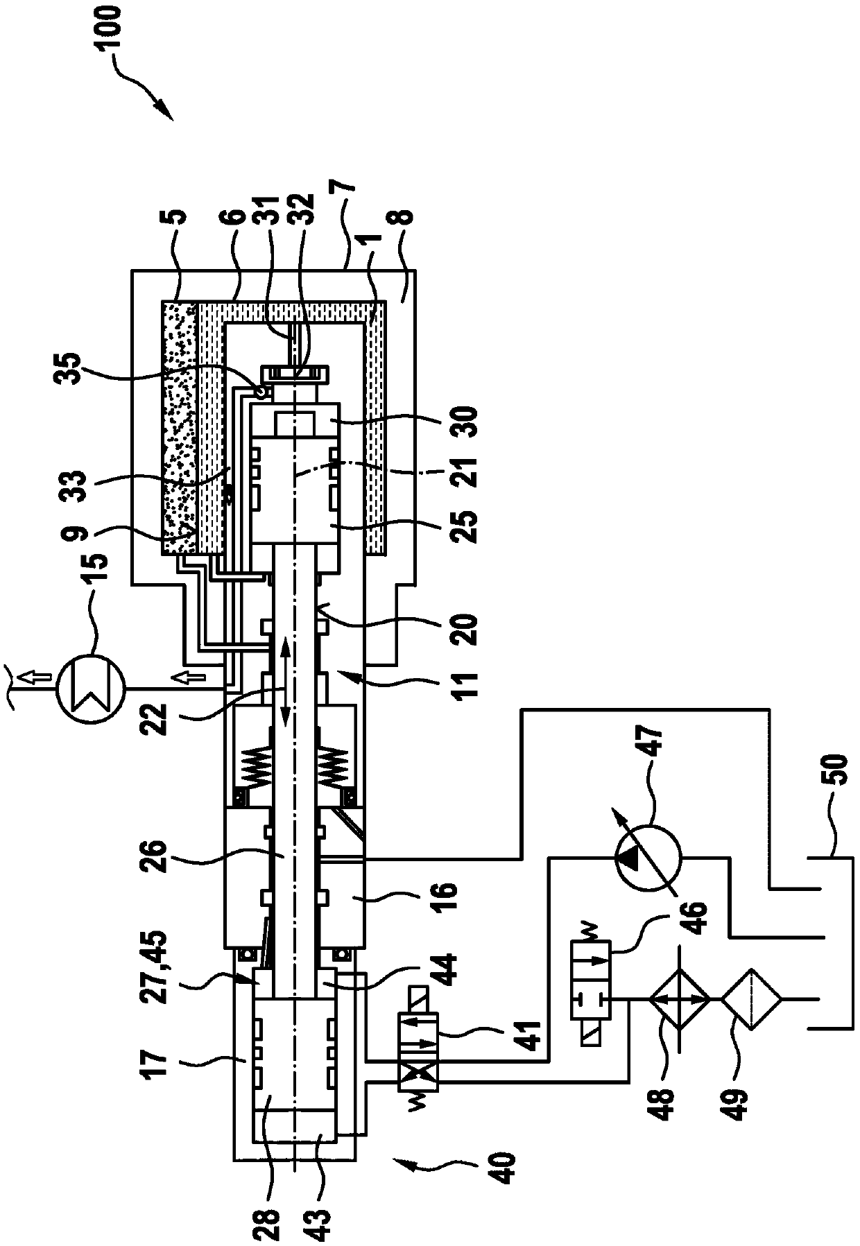
[0019] exist figure 1 A fuel delivery system 100 for cryogenic fuel 1 is shown in . The fuel 1 is in particular natural gas, and the fuel delivery system 100 is preferably used in an internal combustion engine of a motor vehicle.

[0020] The fuel delivery system 100 has a tank-type container 5 for storing fuel 1 cooled to, for example, -110° C. or lower. For this purpose, the box-like container 5 has an inner box 6 which is surrounded by an outer shell 7 in the form of an intermediate chamber 8 . The intermediate chamber 8 is usually evacuated in order to prevent heat transfer or heat input from the surroundings into the cooled fuel 1 . In the tank container 5 , in particular in the inner tank 6 , the liquid part of the fuel 1 reaches the filling level 9 . Above the fill level 9 the fuel 1 is present in the gaseous phase.

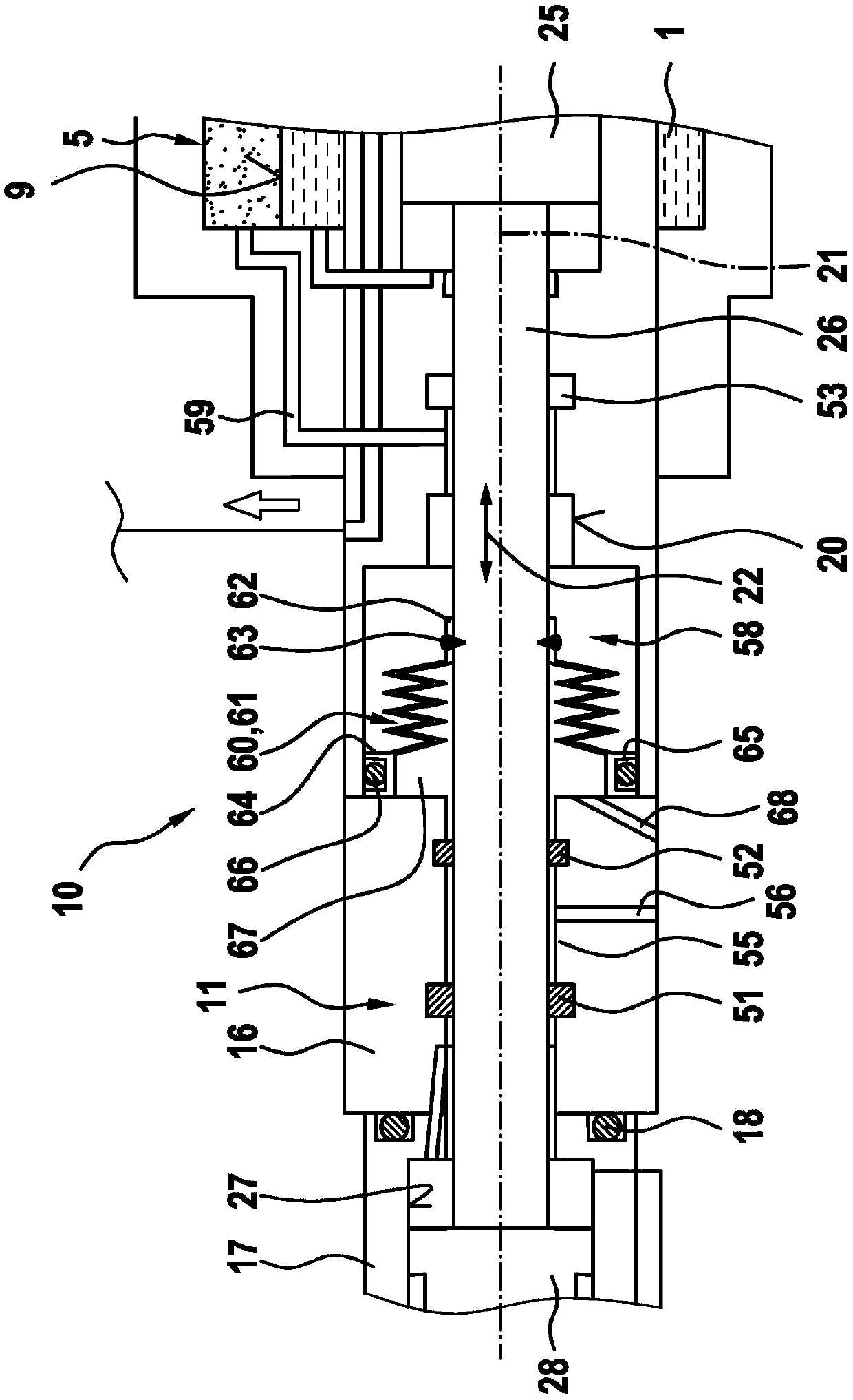
[0021] The tank container 5 , or its inner tank 6 and outer casing 7 , is passed through by a delivery pump 10 which has a pump housing 11 . In the r...


PUM


Abstract

The invention relates to a delivery pump (10) for cryogenic fuels (1), comprising a pump casing (11) inside which a pump piston (25) is arranged in such a way as to be able to reciprocate within a pump chamber (30); the pump piston (25) is connected to a drive (40) for the pump piston (25) by means of a piston rod (26) which is radially guided within a longitudinal bore (20) in the pump casing (11) and which is sealed from the longitudinal bore (20) by at least one sealing device (60), the at least one sealing device (60) being designed to at least reduce leakage of fuel (1) from the pump casing (11).

Description

technical field [0001] The invention relates to a delivery pump for cryogenic fuels according to the preamble of claim 1 . Background technique [0002] Such a feed pump is known from US 7293418 B2. The known delivery pump is characterized in that it protrudes partially into the tank container for cryogenic fuel. For this purpose, known transfer pumps traverse the wall of the box-type container. The drive of the delivery pump, which is arranged outside the tank, is realized, for example, by a hydraulic drive. The hydraulic drive acts on a pump piston connected to the piston rod, which is arranged in the tank-like container on the suction side of the delivery pump. By means of the pump piston, low-temperature fuel is sucked into the pump chamber of the pump housing and is then compressed during the movement of the pump piston in the other direction of movement of the pump piston and supplied, for example, with a pressure increase Give the heating device. The low-temperat...

Claims


Application Information

Patent Timeline
IPC IPC(8): F02M21/02F04B1/04F04B53/02F04B53/14F04B53/16F17C3/02F16L15/00
CPCF02M21/0218F04B9/105F04B15/08F04B53/02F04B53/14F04B53/144F04B53/164Y02T10/30
Inventor I·施托茨F·布雷多D·施尼特格F·策恩德
Owner ROBERT BOSCH GMBH
Why Eureka
Try Eureka