
Weather strip

Active Publication Date: 2006-08-29
TOYODA GOSEI CO LTD
View PDF14 Cites 13 Cited by
  • Summary
  • Abstract
  • Description
  • Claims
  • Application Information

AI Technical Summary

Benefits of technology

[0018]The above structure enhances the effects of the invention still more. Incidentally, the expression “equal to or more than one-fourth of a length from a leading end part of the outer side wall portion to a boundary portion between the connecting portion and the base end part” in the foregoing description of the configuration can be replaced with the expression “equal to or more than one-fourth of a length from a leading end part of the outer side wall portion to a boundary portion between the connecting portion and the base end part and equal to or less than half of the length therefrom”. In the case where, for example, at least a side surface of both the inner side surface and the outer side surface of the projecting portion and a side surface of the outer side wall portion meet substantially at right angles, it is more preferable that the thickness of the base end part of the projecting portion is equal to or more than one-fourth of the length W3, and equal to and less than one-third of the length W3.
[0019]In an embodiment of one of the above structures, thickness of a leading end part of the projecting portion is preferably equal to or more than twice a thickness of the part of the seal portion.
[0020]According to the above, the advantages of the invention are enhanced still more. Incidentally, the expression “equal to or more than twice a thickness of the part of the seal portion” in the foregoing description of the configuration can be replaced with the expression “equal to or more than twice a thickness of the part of the seal portion and equal to or less than three times the thickness of this part”.
[0021]In an embodiment of the above structures of the invention, a projection length from a base end part of the projecting portion to a leading end part thereof is preferably larger than a thickness of the part of the seal portion.
[0022]According to the above, the advantages of the aforementioned structures are enhanced still more.
[0023]The projection length is preferably equal to or more than twice a thickness of the part of the seal portion.

Problems solved by technology

There is a fear of occurrences of drawbacks in that the production cost of a weather strip increases, and that the manufacturing process thereof is complicated.
Thus, there is a fear of occurrences of similar drawbacks.
Moreover, the difference in quality between the extrusion-molding part and the injection-molding part occurs.
This may result in deterioration in the appearance of a vehicle.
Thus, there is a fear of degradation in the quality of the appearance of the vehicle.
Therefore, in the case that such an outside line or a step-like portion is placed on a design surface (for instance, a part that can relatively easily and visually be identified from the outside of a vehicle) of the weather strip 50, there is a fear that deterioration of appearance thereof and degradation in the quality of the appearance thereof occur.
However, there are fears that the production cost of a weather strip increases, and that the process of manufacturing the weather strip is complicated.
However, even when tapering off the film layer toward an end thereof (that is, providing the region in which the quality of the material is gradually changed), it is difficult to eradicate the aforementioned outside line at the end part thereof.

Method used


Image

  • Weather strip
  • Weather strip
  • Weather strip

Examples


first embodiment

[0055]Hereinafter, an embodiment of the invention is described by referring to the accompanying drawings.

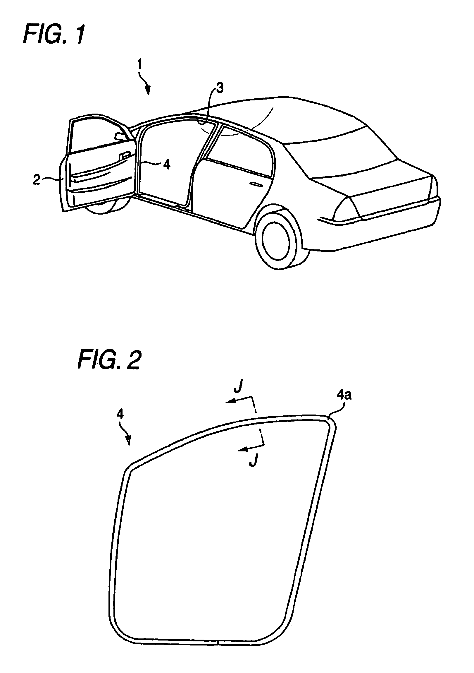
[0056]As shown in FIG. 1, a door 2 is openably and closably provided in a side portion of the automobile 1. A weather strip 4 is attached to the surrounding part of a door opening 3 at the body side corresponding to the door 2. As shown in FIG. 2, the weather strip 4 according to this embodiment is formed like a ring. The weather strip 4 is entirely extrusion-molded.

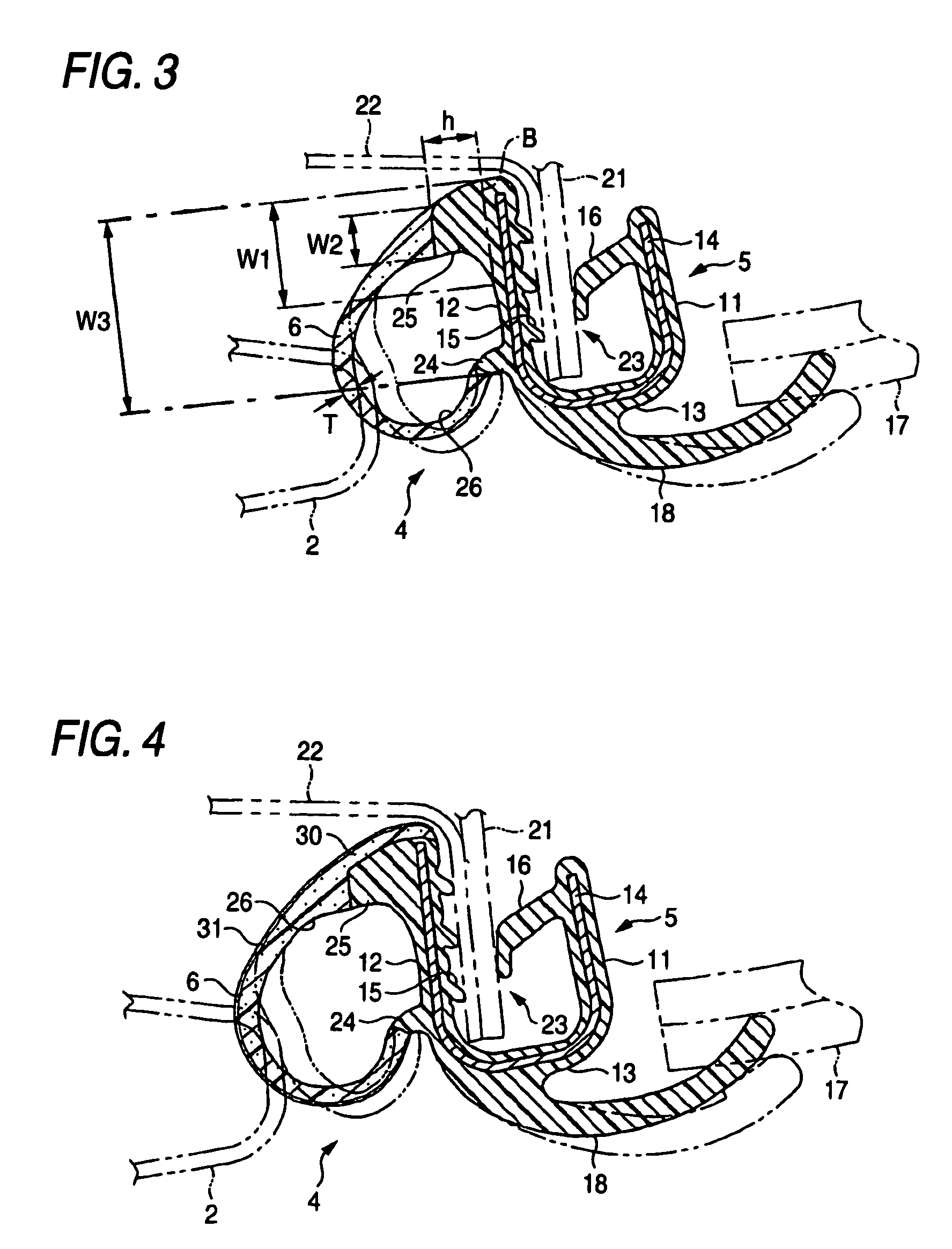
[0057]As shown in FIG. 3, the weather strip 4 has a trimming portion 5 and a seal portion 6.

[0058]The trimming portion 5 has an inner side wall portion 11, an outer side wall portion 12, and a connection portion 13 having a cross-sectionally curved shape. The trimming portion 5 is cross-sectionally substantially-U-shaped as a whole. The trimming portion 5 is made of solid EPDM (ethylene-propylene-diene copolymer) rubber. A metallic insert 14 is embedded therein.

[0059]A plurality of holding lips 15 each extending to th...

second embodiment

[0080]Hereinafter, another embodiment of the invention is described by referring to the accompanying drawings.

[0081]As shown in FIG. 4, the weather strip 4 also has a trimming portion 5 and a seal portion 6.

[0082]The trimming portion 5 has an inner side wall portion 11, an outer side wall portion 12, and a connection portion 13 having a cross-sectionally curved shape. The trimming portion 5 is cross-sectionally substantially-U-shaped as a whole. The trimming portion 5 is made of solid EPDM (ethylene-propylene-diene copolymer) rubber serving as a solid elastic material. A metallic insert 14 is embedded therein.

[0083]A plurality of holding lips 15 each extending to the inside of the trimming portion 5 (that is, to the inside of the vehicle) are formed on the inner surface (that is, the inner side surface) of the outer side wall portion 2 in such a way as to be integral therewith. A holding lip 16 extending to the inside of the trimming portion 5 (that is, to the outside of the vehicle...


PUM


Abstract

A weather strip is attached over the entire surrounding part of a door opening of a vehicle. The weather strip is formed by extrusion-molding, and has a trimming portion having a substantially U-shaped cross section and a hollow seal portion. A first projection portion and a second projection portion are formed on an outer face of an outer side wall part of the trimming portion in such a way as to extend to the outside of the vehicle. The seal portion has an end part connected to a leading end part of the first projection portion, and also has the other end part connected to a leading end part of the second projection portion. The second projection portion is placed at the side of an outer periphery of the weather strip, that is, at the side at which an amount of bending-deformation increases when the corner portion of the weather strip is formed. The second projection portion has a thickness along the outer side wall part and a projection length, each of which is larger than a thickness of a general part of the seal portion. A sponge layer extending from the seal portion may be provided on an outer surface side of the second projection portion.

Description

[0001]The present application is based on Japanese Patent Applications No. 2003-030422 and 2003-031820, which are incorporated herein by reference.BACKGROUND OF THE INVENTION[0002]1. Field of Invention[0003]The present invention relates to a weather strip provided along a surrounding part of a door opening of a vehicle and more particularly to a weather strip having a hollow seal portion.[0004]2. Description of the Related Art[0005]Generally, a weather strip is provided along a surrounding part of a door opening of a vehicle, such as an automobile. As shown in FIG. 5, a weather strip 70 includes a trimming portion 72, which has a substantially U-shaped cross section and held by being fitted into a flange 71 formed in a surrounding part of a door opening, and also includes a hollow seal portion 73 provided in such a way as to protrude from the trimming portion 72. When a door is closed, the seal portion 73 is pressure-contacted to an edge portion of the door, so that the space betwee...

Claims


Application Information

Patent Timeline
IPC IPC(8): F16J15/02B60J10/00B60J10/08
CPCB60J10/0005B60J10/08B60J10/0031Y10S277/921B60J10/16B60J10/24B60J10/80
Inventor KUZUYA, HIROSHIOHASHI, MASAKI
Owner TOYODA GOSEI CO LTD
Learn More