Ski binding, in particular for cross-country skiing

Active Publication Date: 2006-08-29
FISCHER AG GEORG FISCHER AG
View PDF10 Cites 22 Cited by
  • Summary
  • Abstract
  • Description
  • Claims
  • Application Information

AI Technical Summary

Benefits of technology

[0006]It is an object of the present invention to provide measures for counteracting the above-mentioned de

Problems solved by technology

This binding harbors the risk of an unintentional open

Method used


Image

  • Ski binding, in particular for cross-country skiing
  • Ski binding, in particular for cross-country skiing
  • Ski binding, in particular for cross-country skiing

Examples


Embodiment Construction

[0026]Further scope of applicability of the present invention will become apparent from the detailed description given hereinafter. However, it should be understood that the detailed description and specific examples, while indicating preferred embodiments of the invention, are given by way of illustration only, since various changes and modifications within the spirit and scope of the invention will become apparent to those skilled in the art from this detailed description.

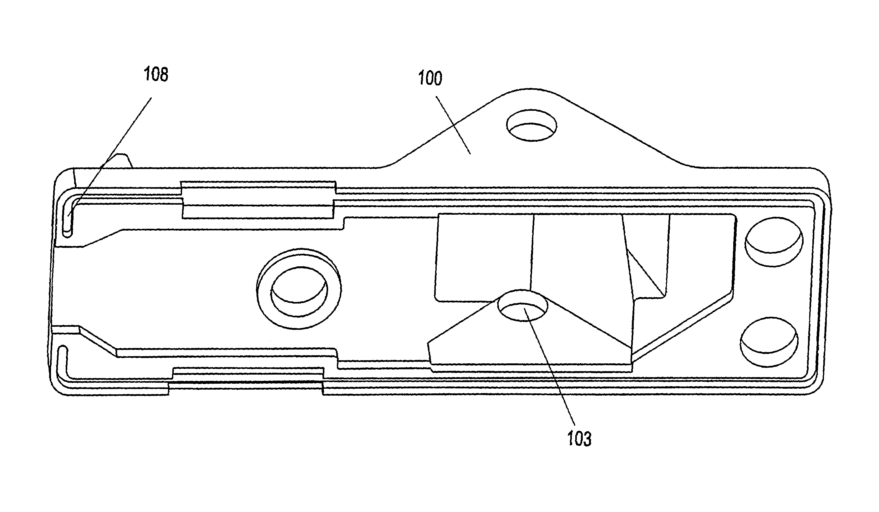
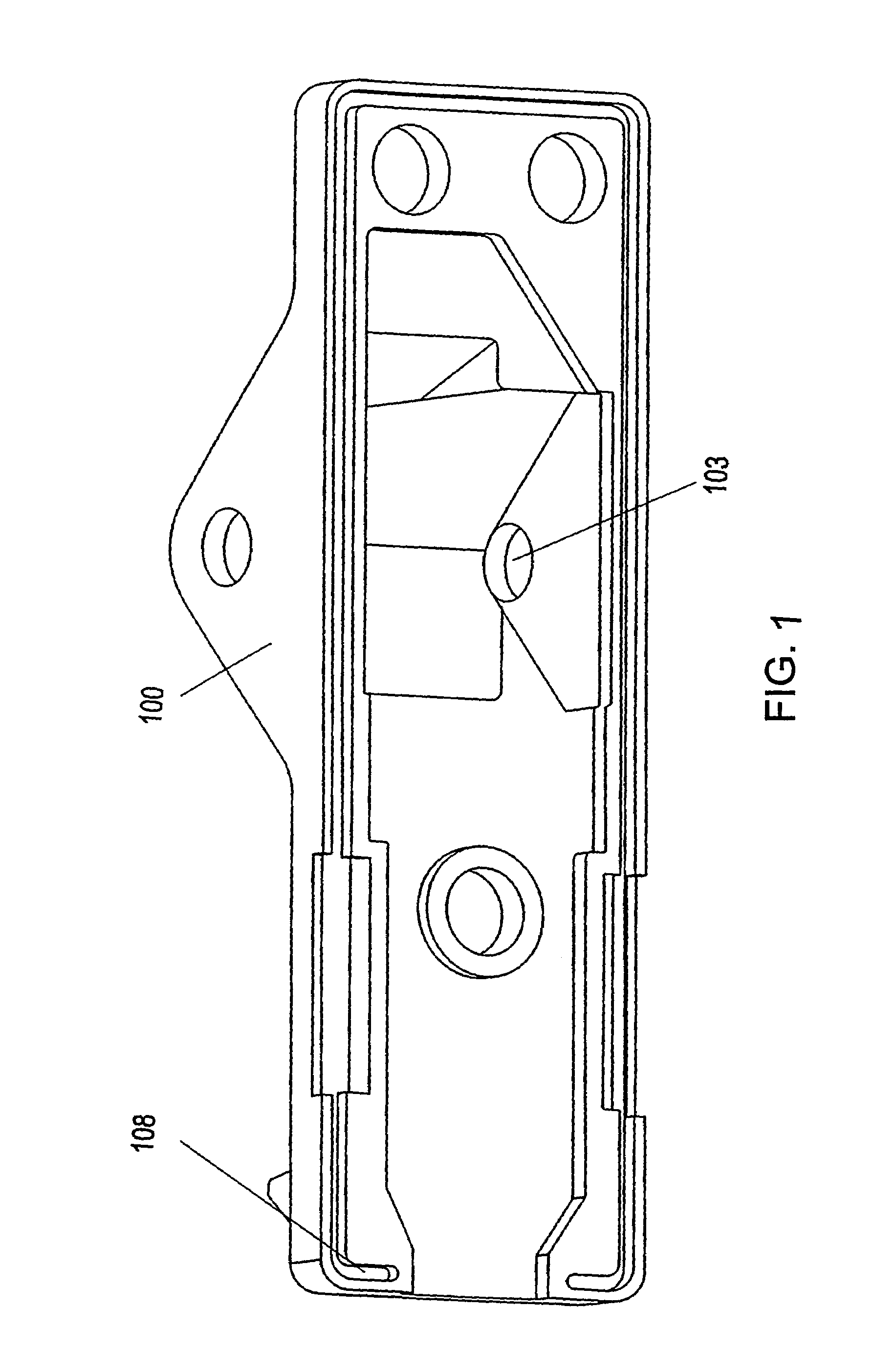
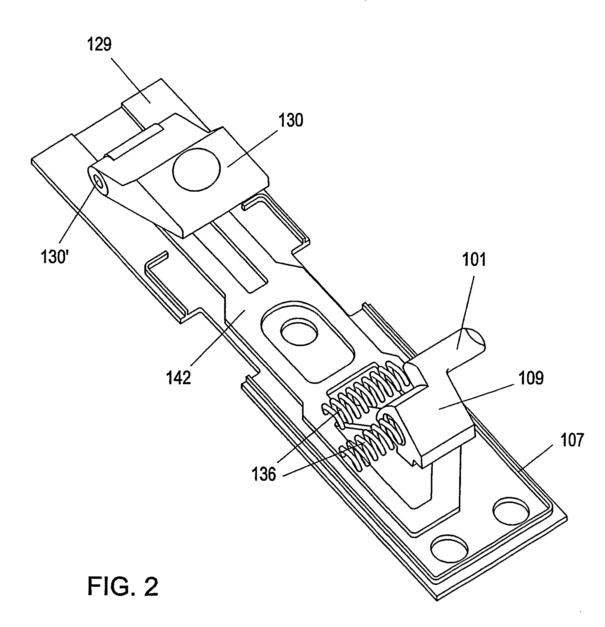
[0027]The binding housing consists of an external housing part 100 which has openings 103 on both sides for receiving the pins 101 of the step-in mechanism.

[0028]The housing 100 of the cross-country ski binding is seated on a base plate 120 which, e.g., is screwed to a ski, on which base plate a sliding element 142 is mounted so as to be displaceable in the running direction, as shown in FIGS. 2 and 3, which sliding element, via a hinge 130′ extending transversely to the running direction, is connected to a lever...


PUM


Abstract

A ski binding, in particular for cross-country skiing, having a sliding element displaceable in the running direction, as well as at least two spring-loaded latching pins movable transversely to the running direction for latching engagement in corresponding fittings in the tip region of the ski boot. Each of the two latching pins is carried by a spring-loaded molded part, the molded parts being oppositely arranged relative to one another and guided in links of the sliding element.

Description

[0001]This is a nationalization of PCT / AT03 / 00100 filed Apr. 4, 2003 and published in German.BACKGROUND OF THE INVENTION[0002]1. Field of the Invention[0003]The present invention relates to a cross-country ski binding having a step-in mechanism.[0004]2. Description of the Related Art[0005]From DE 27 06 111 A, a ski binding of the initially mentioned type is known, in which two transversely movable, spring-loaded pins are provided which are carried by a spring steel wire, which consists of two levers each rotatably held on a rotation axis fixed on a carrier and directed perpendicularly to the ski upper side, which levers comprise pins acting like tongs for a respective engagement in a bearing arranged at the side of the toe-cap. This binding harbors the risk of an unintentional opening of the binding when travelling over uneven ground.SUMMARY OF THE INVENTION[0006]It is an object of the present invention to provide measures for counteracting the above-mentioned deficiency of the know...

Claims


Application Information

Patent Timeline
IPC IPC(8): A63C9/20
CPCA63C9/20
Inventor KOGLER, HANNES
Owner FISCHER AG GEORG FISCHER AG
Why Eureka
Try Eureka