Refillable tape cassette

Inactive Publication Date: 2006-08-29
DYMO (BVBA)
View PDF15 Cites 82 Cited by
  • Summary
  • Abstract
  • Description
  • Claims
  • Application Information

AI Technical Summary

Benefits of technology

[0009]An object of the present invention is thus to provide a refillable tape c

Problems solved by technology

A disadvantage of the known tape cassettes is that once the supply of tape housed in the cassette is printed, the user needs to buy an entirely new cassette, w

Method used


Image

  • Refillable tape cassette
  • Refillable tape cassette
  • Refillable tape cassette

Examples


second embodiment

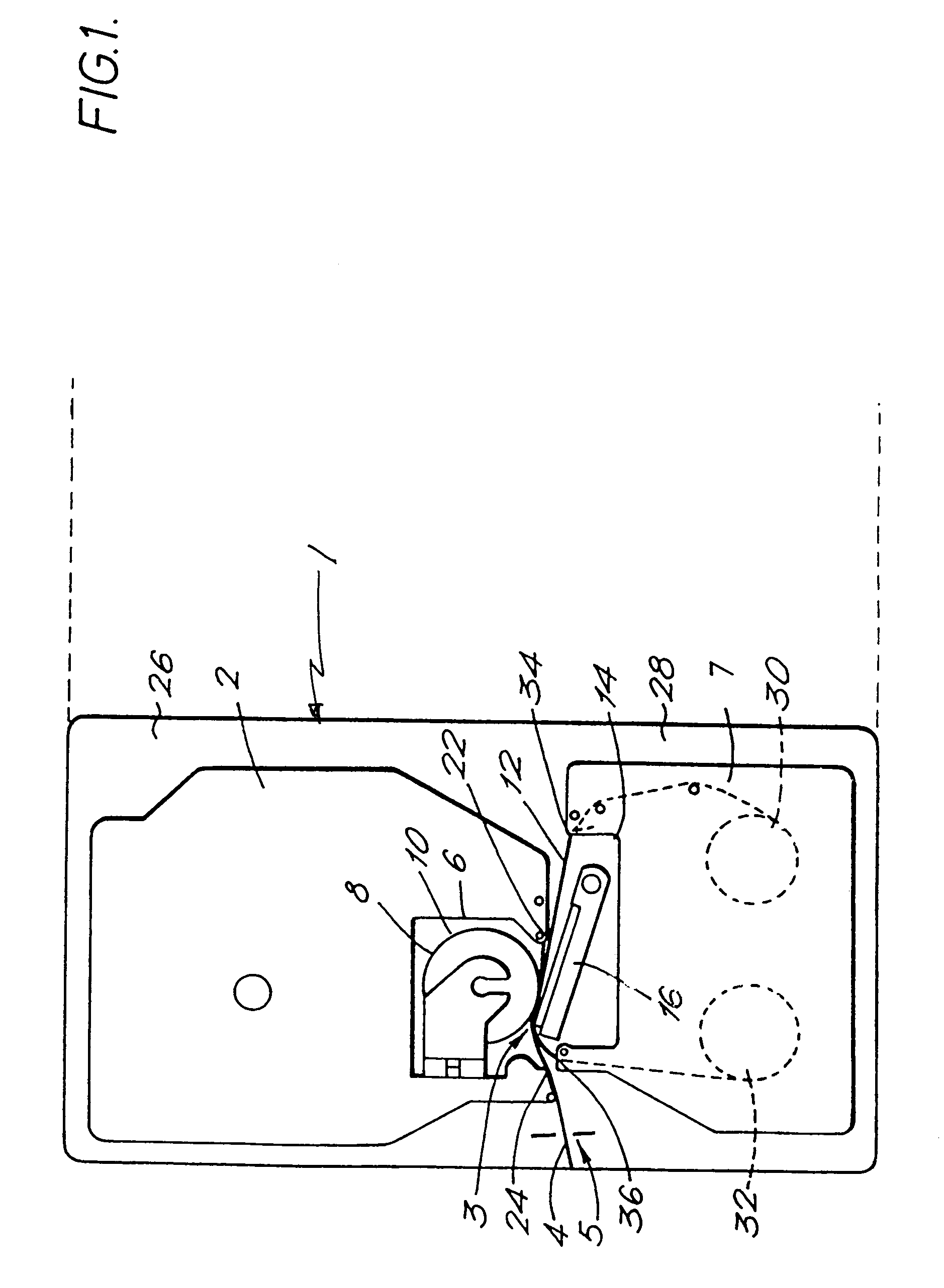
[0051]FIG. 7 illustrates in plan view a cassette bay of a printing device 1 according to the present invention. The cassette receiving bay is shown by the dotted line 26. The cassette bay 26 includes a thermal print head 16 and a platen 8 which cooperated to define a print location 3 in a manner which is known in the art. The print head 16 is pivotable about a pivot point 72 so that it can be brought into contact with the platen 8 for printing and moved away from the platen 8 to enable a cassette to be removed and replaced.

[0052]A cassette inserted into the cassette receiving bay 26 is denoted generally by reference numeral 2. The cassette has a recess 14 for accomodating the print head 16 and holds a supply spool 70 of image receiving tape 4 which comprises an image receiving layer secured to a backing layer by a layer of adhesive. The image receiving tape 4 is guided by a guide mechanism (which is not shown) through the cassette 2 through an outlet, past the print location 3 to a ...

first embodiment

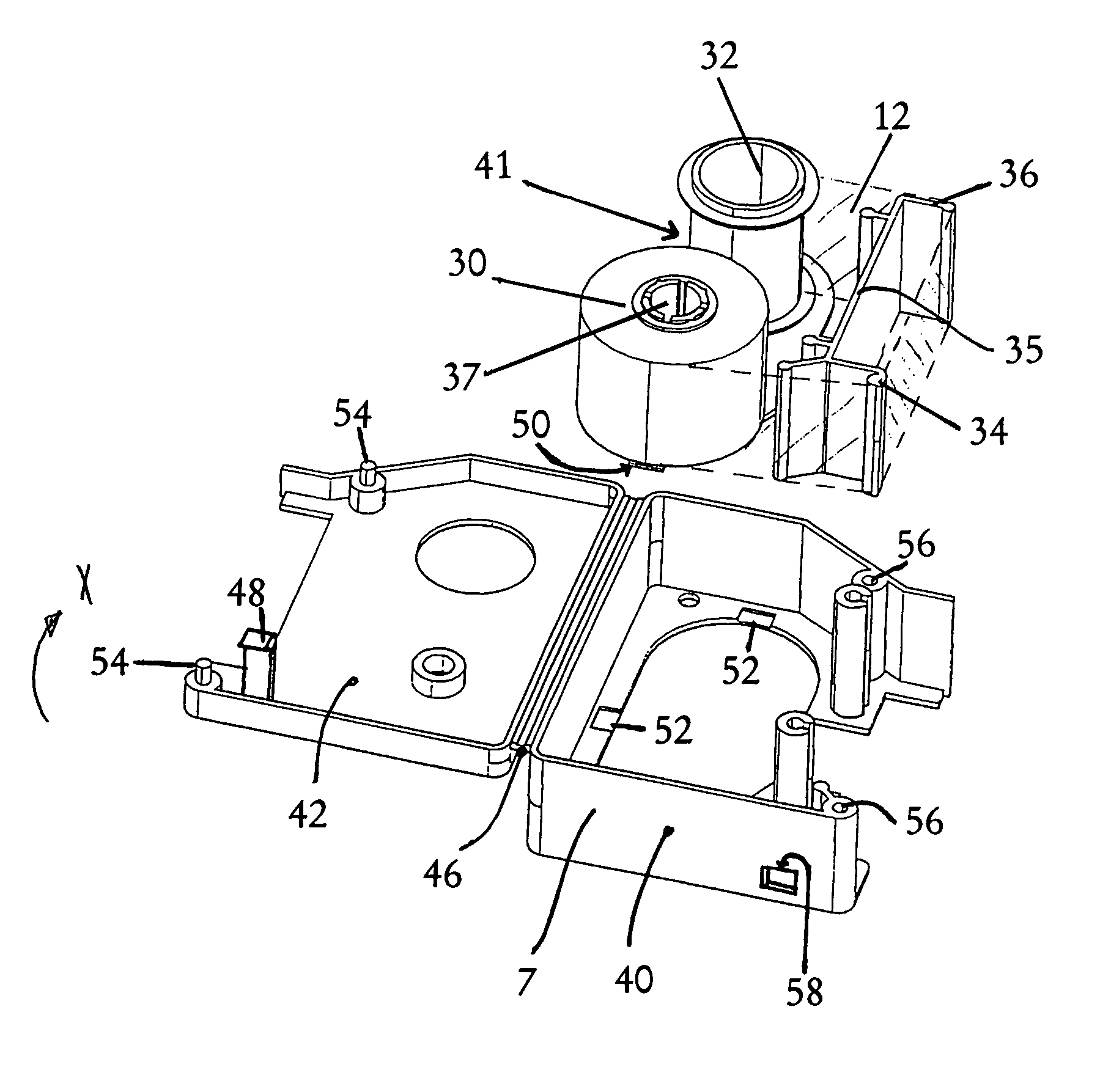
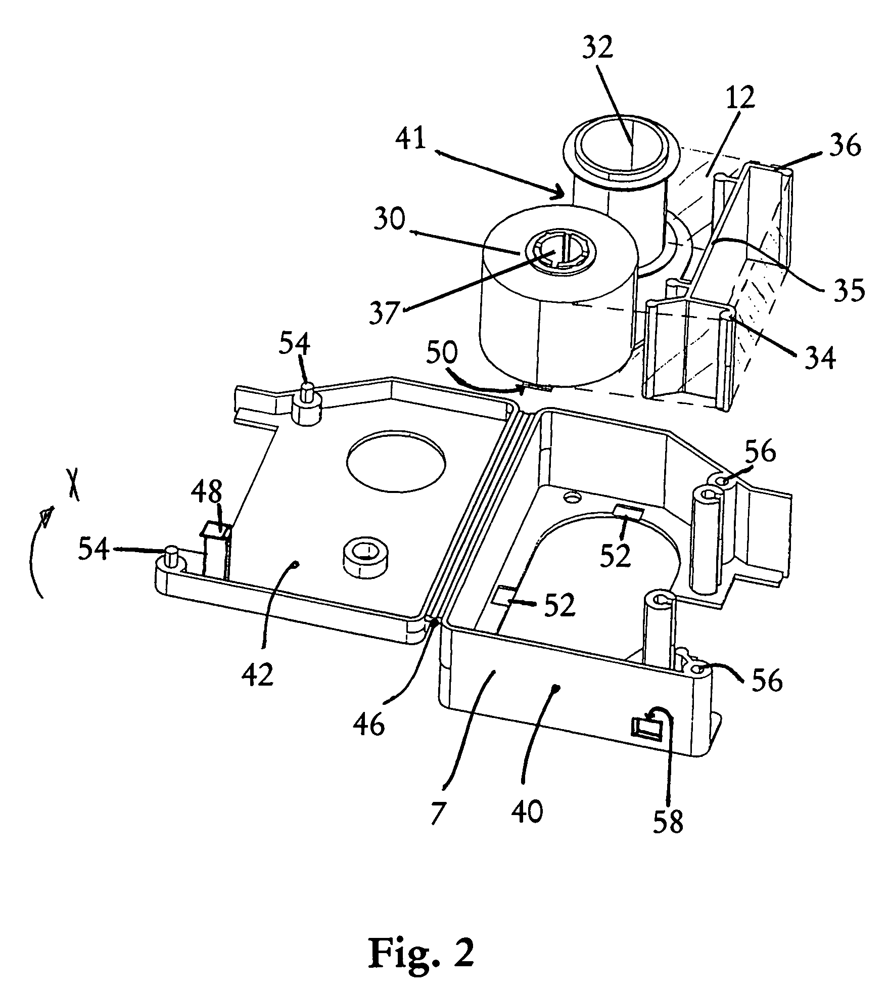
[0054]FIG. 8 illustrates a cassette 2 for use in the printing device 1 illustrated in FIG. 7. It comprises a base 40 which is provided with the features necessary for accomodating the tape 4 and the ink ribbon 12 separately. This cassette 2 has a refillable base with open reel modules and thus offers the user the ability to change the ink / substrate combination without buying a new cassette. For example, ink ribbons of different colours could be swapped at will, to allow different coloured text to be printed onto the same reel of image receiving tape. The embodiment illustrated in FIG. 8 has three main elements: a base 40, an ink ribbon module comprising an ink ribbon supply bobbin 106 and an ink ribbon take up bobbin 104, and an image receiving tape module comprising a tape bobbin 102. The bobbins 102, 104 and 106 are the cores onto which the tape 4, and the ink ribbon 12 is wound or gets wound during printing operations. When the ink ribbon is new, the bobbin 106 and the ink ribbon...


PUM


Abstract

The present invention relates to a refillable tape cassette for accomodating a supply of printable tape. In order to avoid the need for different tape cassettes for different tape widths the tape cassette is capable of selectively housing supplies of tapes of different widths. Alternatively or additionally, the tape cassette can have a housing comprising a base on which the tape supply can be releasably fixed, and a lid fixed to the base, wherein the lid is pivotally mounted to the base by means of a hinge, Further, according to the invention, the windings of refill tape units are held together by means of a strip of adhesive or by means of wax on the axial ends of the units, or by scuffing the backing layer of an image receiving tape which is broader than the image receiving layer.

Description

BACKGROUND OF THE INVENTION[0001]1. Field of the Invention[0002]The present invention relates to a cassette for a tape printer.[0003]2. Background Art[0004]Known tape printing apparatus of the type with which the present invention is generally concerned are disclosed in published European Patent Applications EP-A-0 322 918 and EP-A-0 322 919 (Brother KK) and EP-A-0 267 890 (Varitronic). The printers each include a printing device having a cassette receiving bay for receiving a cassette or tape holding case. In EP-A-0 322 918, the tape holding case houses an ink ribbon, a transparent image receiving tape and a double-sided adhesive tape which is secured at one of its adhesive coated sides to the image tape after printing and which has a backing paper peelable from its other adhesive side. With both these apparatus, the image transfer medium (ink ribbon) and an image receiving tape (substrate) are in the same cassette.[0005]The present invention was developed as a different type of ta...

Claims


Application Information

Patent Timeline
IPC IPC(8): B41J15/02B41J15/04B41J32/00B41J33/52B41J35/28
CPCB41J32/00B41J35/28B41J33/52
Inventor HEYSE, GEERTDAY, ROBERTSIMS, CHARLES ROBERT
Owner DYMO (BVBA)
Why Eureka
Try Eureka