
Method for preparing catalysts

a catalyst and catalyst solution technology, applied in the field of catalyst preparation, can solve the problems of poorly distributed catalysts, pore volume impregnation is not readily applicable to monolithic catalyst supports, and interaction between the surface of the support and the catalyst solution, so as to achieve unit selectivities and reduce chemisorption rates

Inactive Publication Date: 2006-08-29
CORNING INC
View PDF12 Cites 5 Cited by
  • Summary
  • Abstract
  • Description
  • Claims
  • Application Information

AI Technical Summary

Benefits of technology

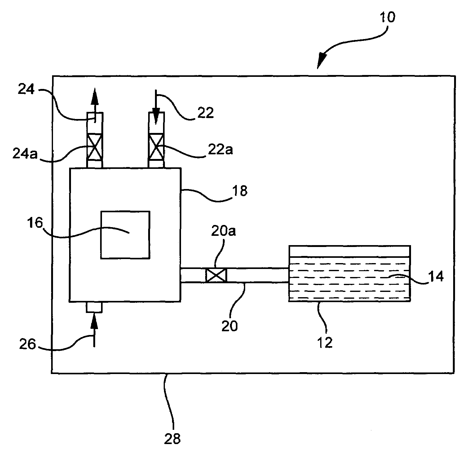
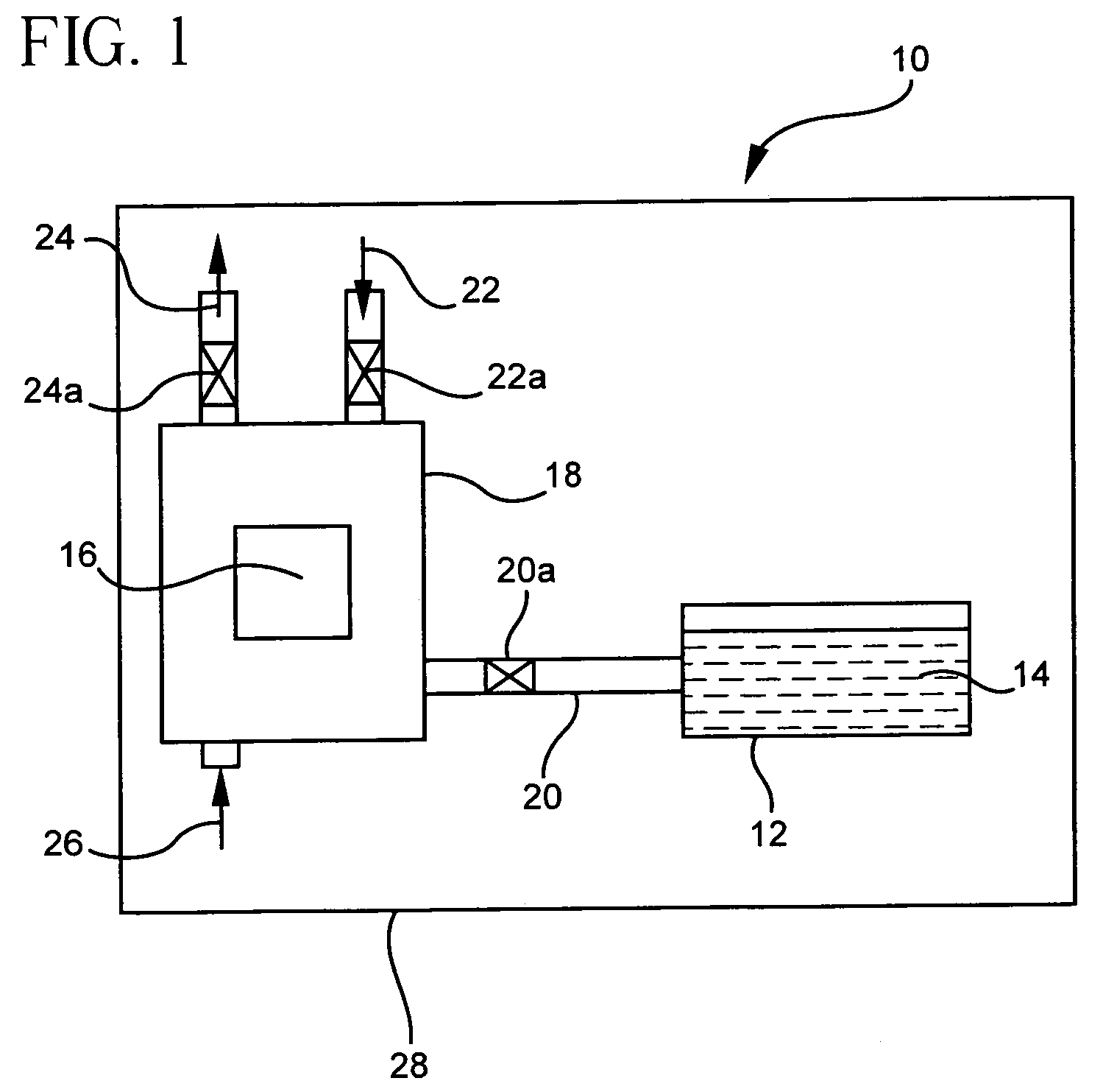
[0008]The present invention meets this need by providing a method for impregnating monolithic substrates with catalytically active materials which attains unit selectivities for all species loaded onto the catalyst substrate. It has been found that by controlling the temperature at which the impregnation technique is carried out, chemisorption rates can be substantially minimized and unit selectivities attained. Selectivity is defined as the ratio of the weight percentages of metal(s) in the substrate in relation to the weight ratio of metal(s) in the catalyst solution.
[0011]It is also desirable that each catalytically active material be present at a calculated pore volume level, where the actual mass of each component loaded onto the porous support (Mpv) is equal to the percent weight of the catalytically active material in the catalyst solution (x) multiplied by the pore volume (PV) of the support and further multiplied by the density of the solution (ρ), or Mpv=x(PV)ρ. Thus, depending on the geometry of the sample, a minimum time may be required to fill the pores with the catalyst solution to achieve the pore volume calculate level.

Problems solved by technology

However, pore volume impregnation is not readily applicable to monolithic catalyst supports due to the complexity and rigidity of their shape.
Simply absorbing the volume of solution equivalent to the volume of the support, generally results in very poorly distributed catalysts.
A disadvantage of the ESI technique, is the interaction that occurs between the surface of the support and the catalyst solution because the various catalytically active materials have different chemisorption rates or react at different rates and to different equilibrium levels.
This leads to “preferential loading” of some metals over others, and unit selectivities cannot be achieved.
This renders the catalyst solution unusable after a period leading to material loss and excessive cost.
Further, to achieve the desired catalyst composition, the impregnation solution must be optimized independently for each process, which results in further costs and inefficient processing.

Method used


Image

  • Method for preparing catalysts
  • Method for preparing catalysts
  • Method for preparing catalysts

Examples


examples

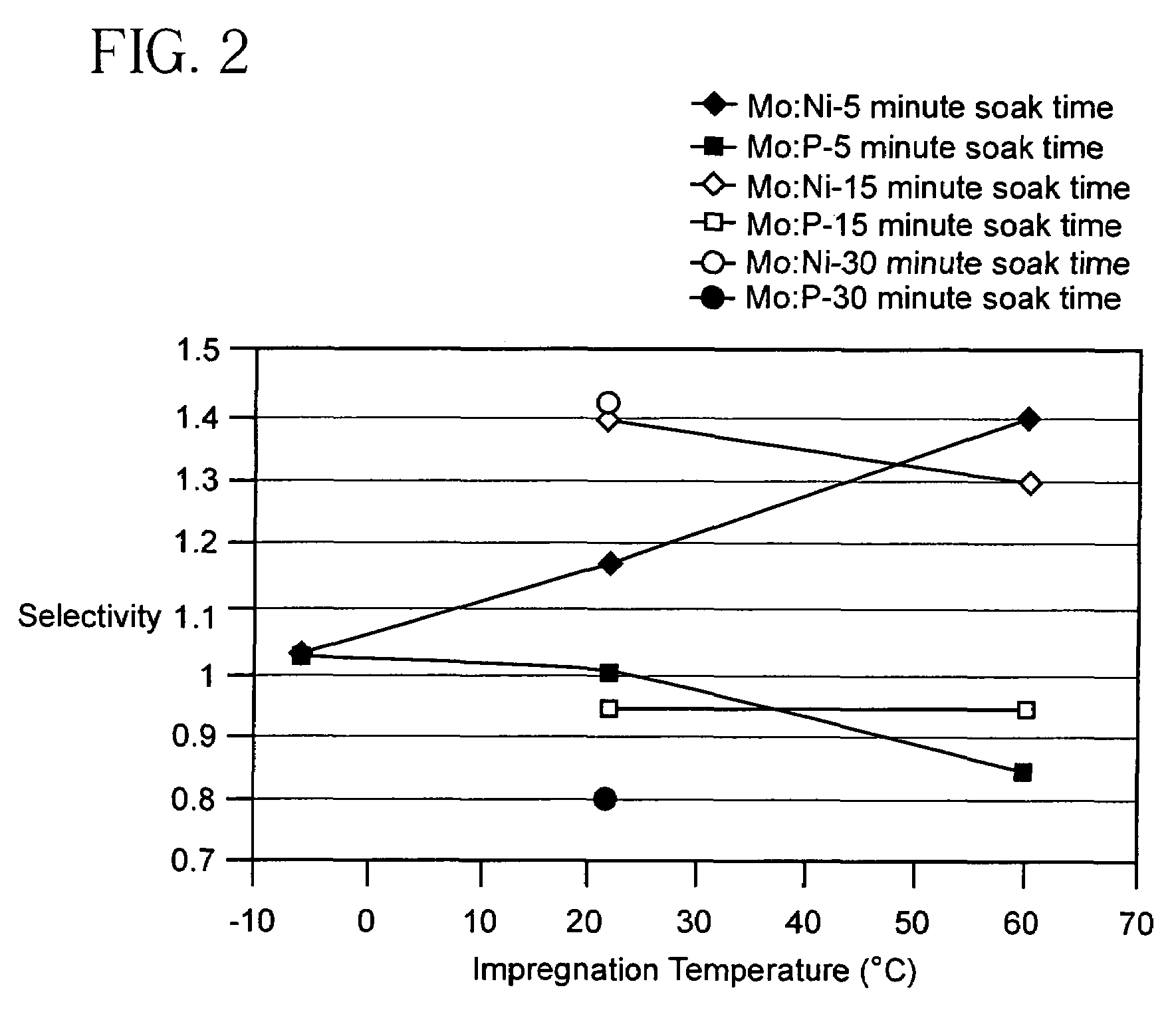
[0029]In a first set of experiments a series of honeycomb substrates composed of gamma alumina (F-1) having properties as presented in Table 1, are impregnated with a catalyst solution containing a mixture of molybdenum oxide, nickel carbonate, and phosphoric acid, and having a Tf equal to −10° C. Catalyst solutions containing combinations of nickel, molybdenum and phosphorus are known for hydrotreating catalyst preparations as described in U.S. Pat. Nos. 6,531,054, 6,576,584, 6,589,908, and 6,620,313.In Table I, the surface area (m2 / g) is measured by nitrogen BET, with pore volume (ml / g), median pore size (Å) and distribution (% pore volume>350Å) being measured by mercury intrusion proximity.

[0030]The impregnation is carried out at temperatures of −6° C., 20° C. and 60° C., and soak times of 5, 15, and 30 minutes. Selectivites for Mo / Ni and Mo / P ratios are calculated from measured weight fractions of Mo, Ni, and P normalized by the weight ratios of Mo / Ni and Mo / P in the initial cat...


PUM

PropertyMeasurementUnit
pressureaaaaaaaaaa
pressureaaaaaaaaaa
temperaturesaaaaaaaaaa

Abstract

A method for impregnating porous monolith supports with catalytically active materials is disclosed. The impregnation is carried out at a temperature which substantially reduces chemisorption rates such that reactions between the monolith substrate and catalytically active materials in the catalyst solution are minimized. The process can be completed in a practical time that allows for unit selectivity of the weight ratio of catalytically active materials in the substrate to the weight ratio of catalytically active materials in the catalyst solution.

Description

BACKGROUND OF THE INVENTION[0001]The present invention relates to a method for preparing catalysts, and in particular to a method for impregnating monolithic catalyst supports, such as honeycomb structures, which substantially reduces preferential loading and achieves unit selectivity.[0002]Catalyst impregnation is one of the most crucial steps for preparing industrial catalysts, such as those useful in hydrotreating applications. Generally, high surface area oxide substrates or supports are loaded with one or more catalytically active materials, such as noble and / or base metals. Two widely-known impregnation techniques include pore volume impregnation (PVI), and excess solution impregnation (ESI).[0003]PVI which is used with pellets or beads catalyst supports, involves the use of a catalyst solution of a volume equivalent to or slightly less than the total pore volume of the supports. The liquid solution penetrates and fills up the support pore volume, delivering a specific amount ...

Claims


Application Information

Patent Timeline
Patent Type & Authority Patents(United States)
IPC IPC(8): B05D1/18B05D3/00B01J20/00B01J21/04B01J21/08B01J21/12B01J21/14B01J23/00B01J23/02B01J23/40B01J23/42B01J27/19B01J35/04B01J37/02
CPCB01J35/04B01J37/0215B01J37/0211B01J37/0201
Inventor DAWES, STEVEN B.MAZUMDER, PRANTIK
Owner CORNING INC
Learn More