

Hybrid charging system
- Summary
- Abstract
- Description
- Claims
- Application Information
AI Technical Summary
Benefits of technology
Problems solved by technology
Method used
Image

Examples
Embodiment Construction
[0009]It is an objective of the invention to provide a simple and economic charging system providing wired and wireless charging capability.
[0010]This objective is achieved by the subject-matter of the independent claims. Further exemplary embodiments are evident from the dependent claims and the following description.
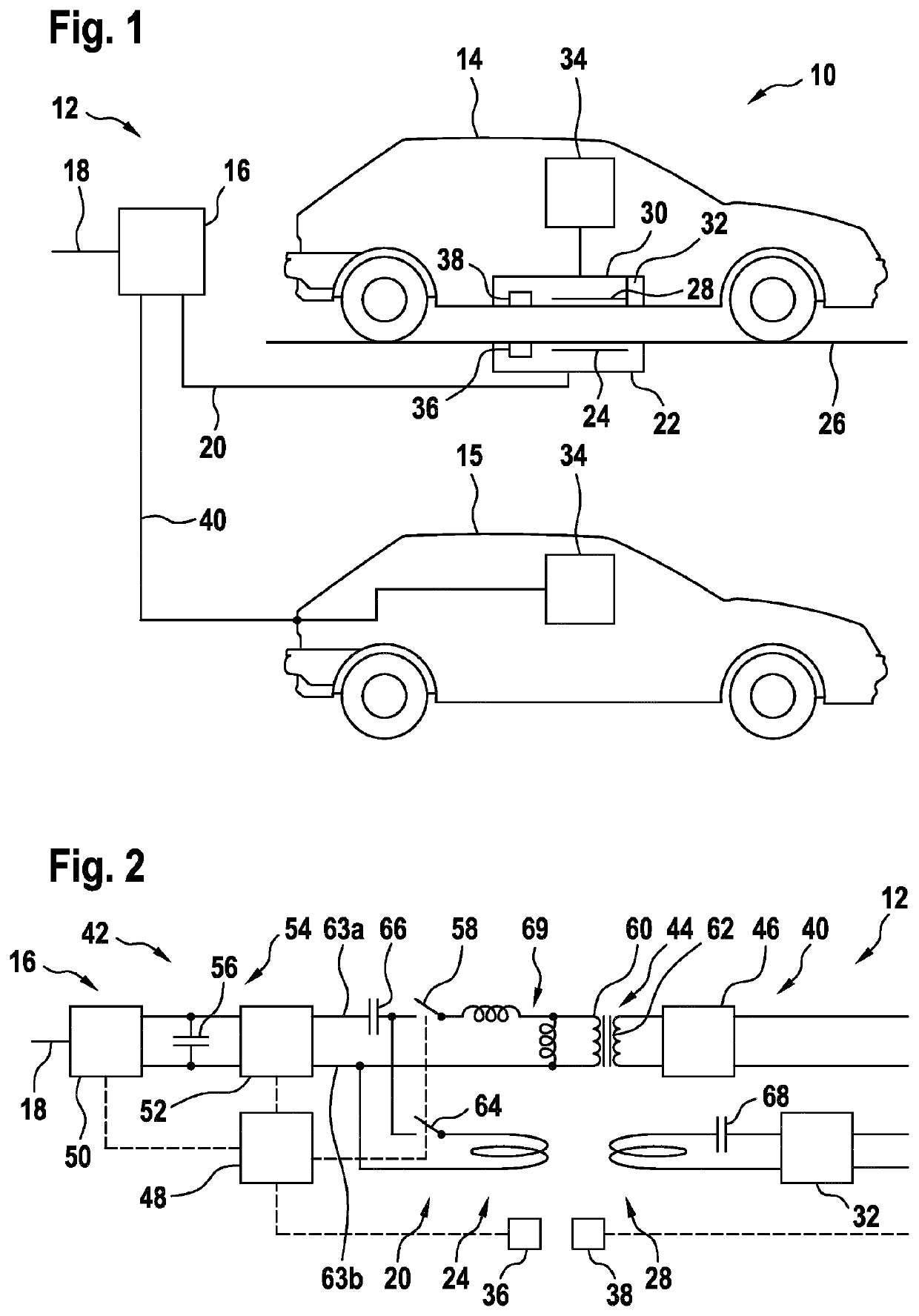
[0011]An aspect of the invention relates to a hybrid charging system for electric vehicles. In this context, the term “hybrid” may refer to a charging system that is adapted for charging with the wired and wireless power transfer. An electric vehicle may be a street vehicle that may be driven with an electric motor, which is supplied by a battery. The hybrid charging system may be used for charging the battery. Also a hybrid vehicle, i.e. a vehicle with a combustion engine and an electrical motor, may be seen as an electric vehicle.
[0012]According to an embodiment of the invention, the hybrid charging system comprises an AC-to-AC converter connectable to an electric AC...
PUM
 Abstract
Description
Claims
Application Information