Low Temperature High Efficiency Condensing Heat Engine for Propelling Road Vehicles

a high-efficiency condensing heat engine and high-efficiency technology, which is applied in the direction of machines/engines, mechanical equipment, lighting and heating apparatus, etc., can solve the problems of large waste low efficiency inherent in basic design and operating principles, and large waist of heat energy generated by burning gasoline. achieve high efficiency and high power density

Inactive Publication Date: 2011-11-17
MINOVITCH MICHAEL ANDREW
View PDF8 Cites 6 Cited by
  • Summary
  • Abstract
  • Description
  • Claims
  • Application Information

AI Technical Summary

Benefits of technology

[0005]A closed-cycle, low-temperature, non-polluting, condensing heat engine and operating method is provided for propelling road vehicles at high efficiencies and high power densities. The working fluid comprises a phase changing gas having a critical temperature close to the temperature of the natural atmosphere at ambient temperature, but above the temperature of evaporating water. This enables the engine to operate cyclically as a closed-cycle condensing heat engine where the high temperature heat reservoir is maintained at relatively low temperatures not far above ambient temperature by burning small amounts of a clean burning liquified natural gas (LNG) such as Propane, Butane, or Pentane. The low temperature heat reservoir (heat sink) is created artificially at sub-ambient temperatures by evaporating small amounts of water.

Problems solved by technology

Unfortunately, this low efficiency is inherent in the basic design and operating principles of these engines.
Most of the energy generated by the burning fuel (gasoline) is wasted to keep the engine from self-destructing.
The result is a huge waist of the heat energy generated by the burning gasoline while simultaneously generating enormous amounts of pollution that is toxic to life and harmful to the environment.
Since both of these temperatures are fairly high in internal combustion engines, this equation shows why they are inherently inefficient.

Method used


Image

  • Low Temperature High Efficiency Condensing Heat Engine for Propelling Road Vehicles
  • Low Temperature High Efficiency Condensing Heat Engine for Propelling Road Vehicles
  • Low Temperature High Efficiency Condensing Heat Engine for Propelling Road Vehicles

Examples


Embodiment Construction

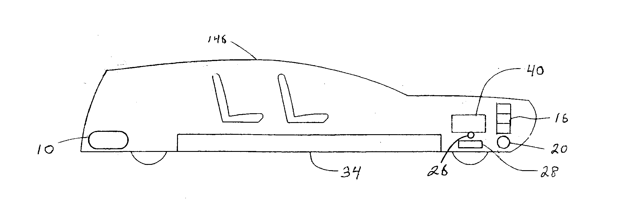
[0020]The invention presented herein is a silent, non-polluting, closed-cycle condensing heat engine for propelling road vehicles operating at low temperatures designed to enable essentially all of the input heat energy to be absorbed by the working fluid to achieve a fuel efficiency (miles per gallon of fuel consumed) far exceeding that of conventional internal combustion engines that are currently used for propelling passenger carrying automobiles. This is achieved by shifting the operating temperatures significantly downward such that the low temperature heat reservoir is at a sub-ambient temperature that is maintained by evaporating small amounts of water utilizing the fact that water has an unusually high latent heat of vaporization. This enables the temperature of the high temperature heat reservoir to be shifted significantly downward that can be maintained by burning small amounts of a clean burning fuel where almost all of the heat of combustion is used for heating the work...


PUM


Abstract

A non-polluting, closed-cycle condensing heat engine and operating method is provided for propelling road vehicles at high efficiencies and high power densities by using a phase-changing working fluid having a critical temperature close to the natural ambient temperature of the surrounding atmosphere and shifting the high temperature heat reservoir downward by several hundred degrees by creating an artificial low temperature heat reservoir below ambient temperature by evaporating water. By isentropically compressing the liquefied working fluid at sub-ambient temperatures to very high pressure utilizing the fact that water has an unusually high latent heat of evaporation, and heating it to a compressed gas at a relatively low temperature in the high temperature heat reservoir by burning small amounts of fuel, it is possible for the engine to operate at high power densities by expanding the compressed gas back to the initial sub-ambient temperature where it is re-condensed to propel road vehicles several hundred miles on a tank of water holding only 40 gallons using a small fraction of the amount of fuel used by vehicles propelled by conventional internal combustion engines.

Description

BACKGROUND [0001]It is a well known fact that the internal combustion engine used for propelling road vehicles has an energy efficiency of only about 12%. Unfortunately, this low efficiency is inherent in the basic design and operating principles of these engines. Most of the energy generated by the burning fuel (gasoline) is wasted to keep the engine from self-destructing. In order to understand this little known technical fact, it is important to understand the basic operating principles of these engines.[0002]An internal combustion engine used for propelling conventional passenger-carrying automobiles consists primarily of a plurality of stationary cylinders containing a moving piston which form combustion chambers for generating compressed gas of variable volume. Both of these parts are constructed of metal. Since the gas temperatures generated inside the cylinders by the burning fuel are well above the ability of un-cooled metals to withstand, the cylinders of an internal combu...

Claims


Application Information

Patent Timeline
Patent Type & Authority Applications(United States)
IPC IPC(8): F01K13/00F25B9/00F01K23/00
CPCF01K25/10F01K15/02
Inventor MINOVITCH, MICHAEL ANDREW
Owner MINOVITCH MICHAEL ANDREW
Why Eureka
Try Eureka