Vacuum circuit breaker, vacuum circuit breaker contact slow closing method, and contact erosion measuring method and contact gap length setting method using that slow closing method

a technology of vacuum circuit breakers and slow closing methods, which is applied in the direction of contact mechanisms, air-break switches, instruments, etc., can solve the problems of reducing workability when setting the gap length, inability to fine-tune the gap length, and increasing costs, so as to achieve the effect of accurately setting the contact gap length, moving simply, slowly and accurately, and measuring accurately

Active Publication Date: 2006-08-29
MITSUBISHI ELECTRIC CORP
View PDF8 Cites 31 Cited by
  • Summary
  • Abstract
  • Description
  • Claims
  • Application Information

AI Technical Summary

Benefits of technology

[0013]The present invention aims to solve the above problems and an object of the present invention is to provide a vacuum circuit breaker disposed so as to be fixed inside a switchgear, a vacuum circuit breaker contact slow closing method, and a contact erosion measuring method and contact gap length setting method using that slow closing method enabling vacuum circuit breaker contact erosion to be measured accurately without using specialized equipment.
[0015]According to the present invention, rotational motion of the adjusting rod is converted to rectilinear motion by the internal thread member. Then, the vacuum interrupter contact moves from an open state to a closed state due to this converted rectilinear motion. Thus, because the movable contact can be moved simply by rotating the adjusting rod, the movable contact can be moved simply, slowly, and accurately without using specialized dedicated equipment, and the position of the movable contact can also be fixed simply by stopping the rotation of the adjusting rod. Consequently, because movement of the movable contact can be stopped at a contact closing point, the influence of squeezing originating from a compression spring can be removed, enabling contact erosion to be measured accurately. In addition, because a contact gap length can be set by rotating the adjusting rod in reverse to move the contact to the open state from the closing point, the influence of contact erosion conditions can be removed, enabling the contact gap length to be set accurately.

Problems solved by technology

(1) Because the gap length is set by interposing the spacer between the opening and closing lever and the damper, fine adjustment of the gap length is not possible;
(2) Because the contacts are moved by a lever principle using a manually-operated handle, workability is reduced when setting the gap length;
(3) Specialized equipment is required when performing slow closing, increasing costs; and
(4) The construction of an operating mechanism portion is complicated, making workability poor in slow closing methods in which the operating mechanism portion is operated.

Method used


Image

  • Vacuum circuit breaker, vacuum circuit breaker contact slow closing method, and contact erosion measuring method and contact gap length setting method using that slow closing method
  • Vacuum circuit breaker, vacuum circuit breaker contact slow closing method, and contact erosion measuring method and contact gap length setting method using that slow closing method
  • Vacuum circuit breaker, vacuum circuit breaker contact slow closing method, and contact erosion measuring method and contact gap length setting method using that slow closing method

Examples


embodiment 1

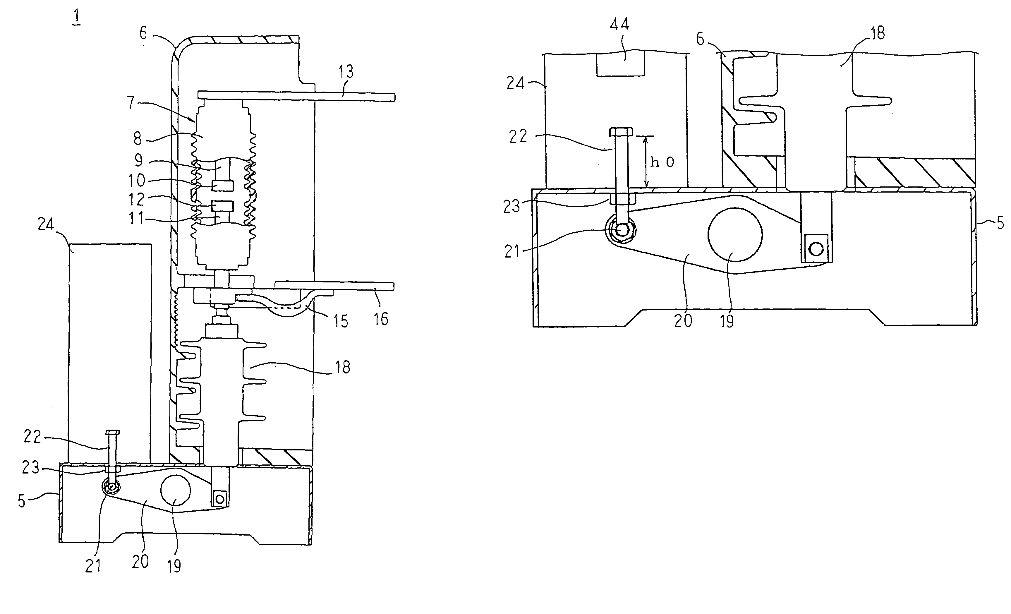
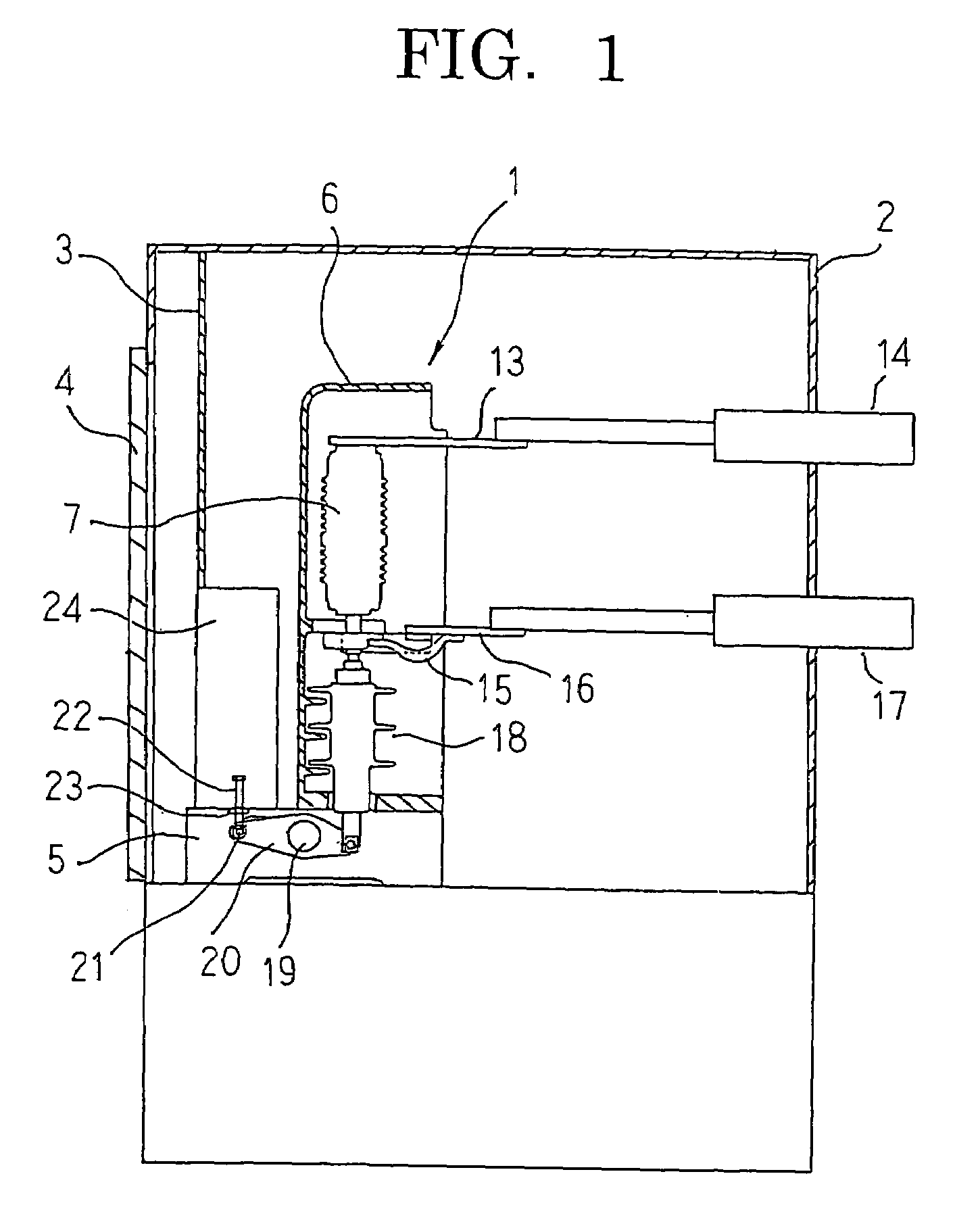
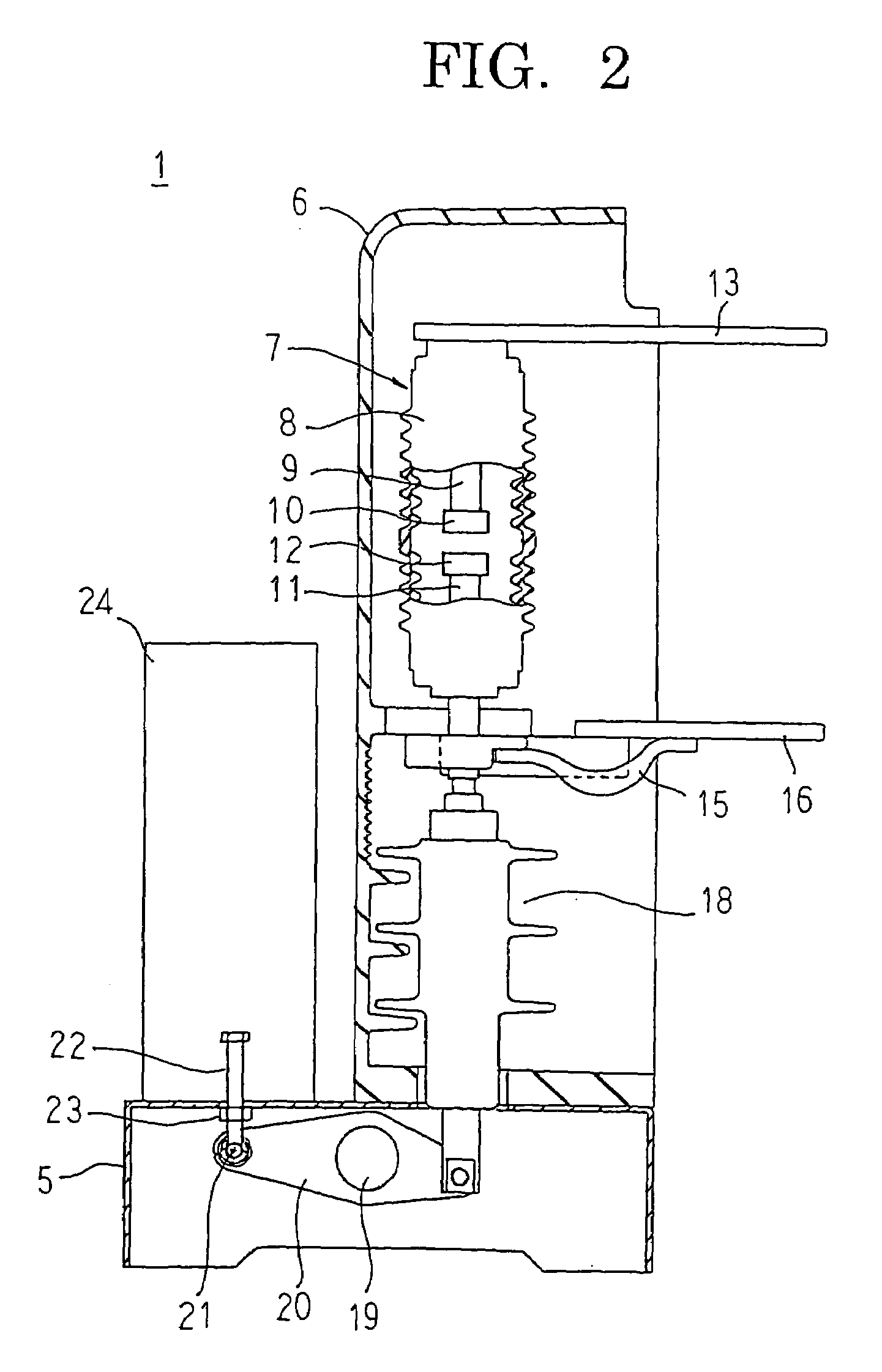
[0029]FIG. 1 is a partially cut-away side elevation showing a vacuum circuit breaker according to Embodiment 1 of the present invention, FIG. 2 is a partially cut-away side elevation showing part of the vacuum circuit breaker according to Embodiment 1 of the present invention, FIG. 3 is a partially cut-away top plan showing the vacuum circuit breaker according to Embodiment 1 of the present invention, FIG. 4 is a cross section showing a vicinity of an adjusting bolt in the vacuum circuit breaker according to Embodiment 1 of the present invention, FIG. 5 is a diagram schematically explaining an action of an operating mechanism portion in the vacuum circuit breaker according to Embodiment 1 of the present invention, FIG. 6 is a diagram explaining a contact contacting position measuring method in the vacuum circuit breaker according to Embodiment 1 of the present invention, FIG. 7 is a partial cross section showing an open state of the contacts in the vacuum circuit breaker according t...

embodiment 2

[0058]FIG. 9 is a perspective showing a determining gauge used in a contact erosion measuring method in a vacuum circuit breaker according to Embodiment 2 of the present invention, and FIGS. 10A and 10B are partial cross sections showing the contact erosion measuring method in the vacuum circuit breaker according to Embodiment 2 of the present invention, FIG. 10A showing a case in which the contact erosion is less than or equal to a specified value, and FIG. 10B showing a case in which the contact erosion exceeds the specified value.

[0059]In Embodiment 2, measurement of contact erosion is performed using a determining gauge 46 made into a rectangular parallelepiped having a predetermined thickness t, as shown in FIG. 9. Here, the thickness t of the determining gauge 46 is set so as to correspond to an amount of movement of an adjusting bolt 22 required to move contacts from an open state to a closed state when contact erosion has reached a tolerance limit value, for example.

[0060]Ne...

embodiment 3

[0065]FIG. 11 is a partial cross section showing an open state of contacts in a vacuum circuit breaker according to Embodiment 3 of the present invention, and FIG. 12 is a partial cross section showing a closed state of the contacts in the vacuum circuit breaker according to Embodiment 3 of the present invention.

[0066]In FIGS. 11 and 12, a block 47 functioning as an internal thread member has: an internal thread portion 48 formed in a penetrating aperture; and a U-shaped hook portion 49 formed on an outer wall surface such that the hook is parallel to the penetrating aperture. The block 47 is hooked onto a pin 21 such that the hook portion 49 points downward, and an adjusting bolt 22 is screwed into the external screw thread portion 48 from below. Here, the block 47 mounted to the pin 21 is configured such that a central axis of the adjusting bolt 22 is parallel to a closing and opening direction of contacts.

[0067]Next, a contact erosion measuring method using a contact slow closing...


PUM


Abstract

An adjusting bolt is screwed into a nut attached to a dolly, and is disposed such that a central axis thereof is parallel to a closing and opening direction of a contact. A lever is attached to a shaft. An electrically-insulating rod is coupled to a first end of the lever, and a pin is mounted to a second end of the lever. The adjusting bolt is turned and lowered to lower the pin. The lever and the shaft are pivoted by the lowering of the pin, and the electrically-insulating rod is raised. Thus, a movable contact moves toward a fixed contact, moving the contact from an open state to a closed state.

Description

BACKGROUND OF THE INVENTION[0001]1. Field of the Invention[0002]The present invention relates to a vacuum circuit breaker disposed so as to be fixed inside a switchgear, a vacuum circuit breaker contact slow closing method, and a contact erosion measuring method and contact gap length setting method using that slow closing method.[0003]2. Description of the Related Art[0004]In conventional gas-insulated cubicles, withstand voltages of contacts of vacuum interrupters disposed in sulfur hexafluoride (SF6) gas have hitherto been examined by setting the contacts to a predetermined gap length manually.[0005]In slow closing methods in these conventional gas-insulated cubicles, the gap length of the contacts has been set to a predetermined value by moving a plunger of an electromagnetic apparatus for closing the contacts of the vacuum interrupter using a manually-operated handle and interposing a spacer between an opening and closing lever and a damper operating interdependently with the m...

Claims


Application Information

Patent Timeline
Patent Type & Authority Patents(United States)
IPC IPC(8): H01H33/666
CPCH01H1/0015
Inventor YAMADA, HIROSHIKAGAWA, KAZUHIKO
Owner MITSUBISHI ELECTRIC CORP
Why Eureka
Try Eureka