Heat dissipating structure for an electronic device

a technology of electronic devices and heat dissipation structures, which is applied in lighting and heating apparatus, cooling/ventilation/heating modifications, electrical apparatus, etc., can solve the problems of insufficient heat dissipation results, etc., and achieve the effect of sufficient heat dissipation

Active Publication Date: 2006-08-29
SONY COMPUTER ENTERTAINMENT INC
View PDF15 Cites 20 Cited by
  • Summary
  • Abstract
  • Description
  • Claims
  • Application Information

AI Technical Summary

Benefits of technology

[0011]Since the partition walls are arranged in plural along the inner wall or outer wall, fluctuation of heat transfer from the inner wall to the outer wall occurring along the length of the inner wall or the outer wall is controlled. As a result, the temperature difference between the inner wall, partition walls and the outer wall may be kept small. In other words, a favorable chimney effect can be achieved by making the ambient temperature of the through-holes that function as chimney passageways even, and the air within the through-holes flow smoothly. Accordingly, effectively achieving a heat dissipating effect due to natural convection is possible.
[0027]With the above structure, the heat release from the outer wall of the heat dissipating member increases, further improving the heat dissipating effect overall.

Problems solved by technology

Nevertheless, the conventional structure is not necessarily a suitable structure for the chimney effect, whereby sufficient heat dissipation results could not be obtained.

Method used


Image

  • Heat dissipating structure for an electronic device
  • Heat dissipating structure for an electronic device
  • Heat dissipating structure for an electronic device

Examples


Embodiment Construction

[0035]A preferred embodiment of the present invention is described below with reference to the accompanying drawings. It is noted that like parts or elements are designated by like reference characters in the drawings, without redundant description of the parts or elements.

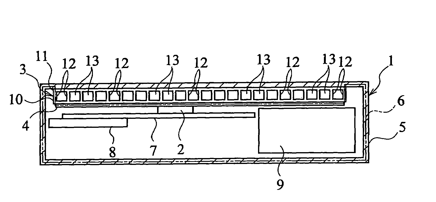
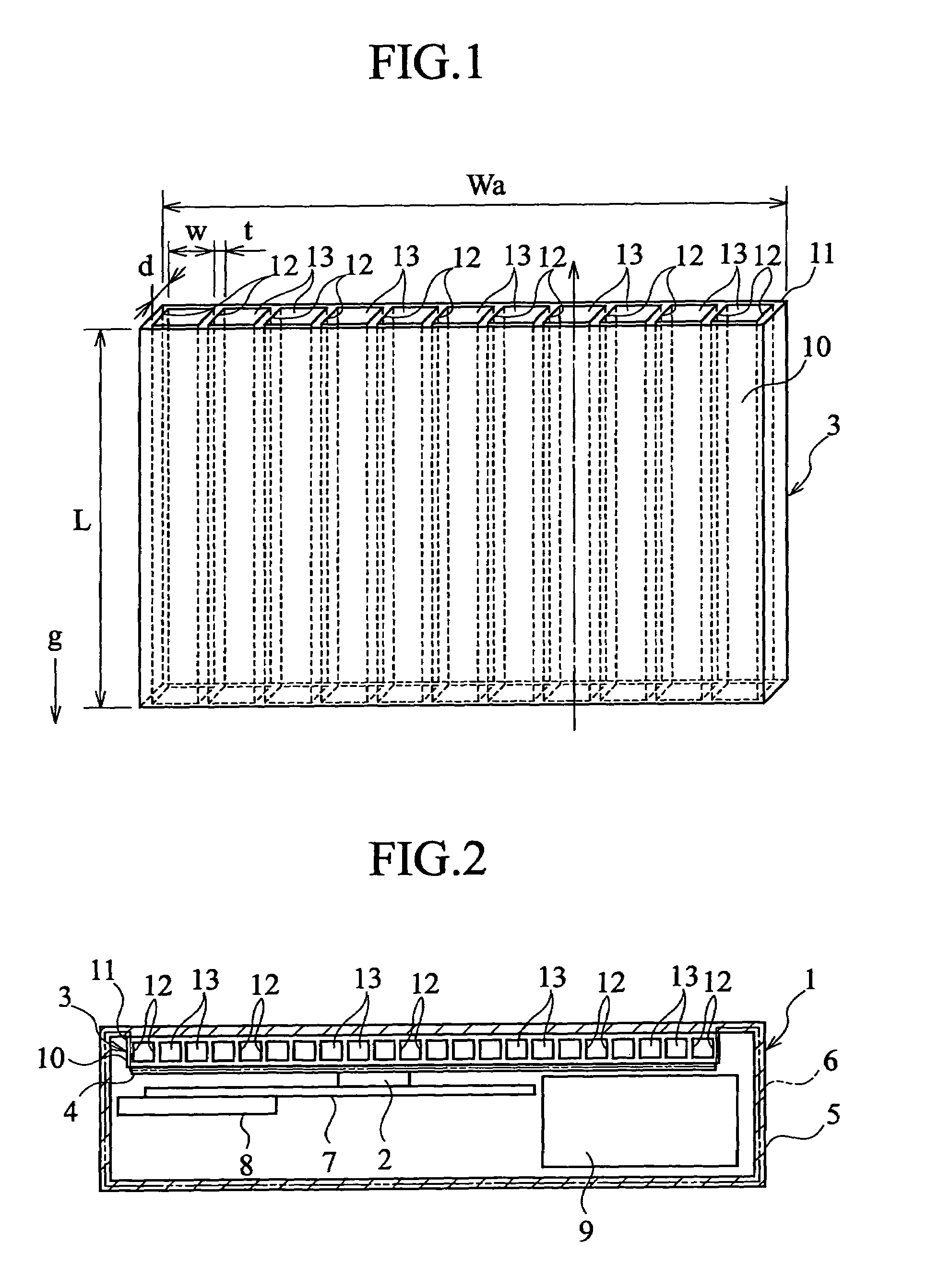
[0036]FIG. 1 is a perspective view of the main parts of a heat dissipating structure for an electronic device according to this embodiment, and FIG. 2 is a general cross-sectional view of the heat dissipating structure of FIG. 1.

[0037]As illustrated in FIG. 2, the heat dissipating structure for an electronic device according to this embodiment includes a case 1, a heat source 2, a heat dissipating member 3, and a spreader 4 which acts as a heat diffusing member.

[0038]The case 1 includes a rectangular tube-shaped peripheral wall 5, and a cover 6 which is fixed at the top and bottom of the peripheral wall 5, where the electronic device is utilized in a state where the peripheral wall 5 is installed in a roughly vert...


PUM


Abstract

A heat dissipating structure for an electronic device includes a heat source and a heat dissipating member. The heat dissipating member has an inner wall, an outer wall, and a plurality of partition walls. The inner wall receives heat transfer from the heat source. The outer wall opposes the inner wall at a distance. The partition walls connect the inner wall and the outer wall, and together with the inner wall and outer wall define a plurality of through-holes which are approximately the same shape and are aligned at roughly regular intervals along the inner wall or the outer wall. The through-holes are arranged along the vertical direction that allows most effective utilization of gravitational influence, and are open to the outside at the upper and lower ends thereof.

Description

BACKGROUND OF THE INVENTION[0001]1. Field of the Invention[0002]The present invention relates to a heat dissipating structure for an electronic device.[0003]2. Description of the Related Art[0004]As a conventional heat dissipating structure for an electronic device, there is one that utilizes natural convection due to the so-called chimney effect. With this structure, the upper and lower ends of a chimney passageway are respectively opened to the outside so as to dissipate heat by utilizing the air that naturally flows upwards through the chimney passageway (for example, see Japanese Patent Application Laid-open No. 9-212258).[0005]Nevertheless, the conventional structure is not necessarily a suitable structure for the chimney effect, whereby sufficient heat dissipation results could not be obtained.SUMMARY OF THE INVENTION[0006]The present invention aims to provide a heat dissipating structure for an electronic device that can achieve a sufficient heat dissipating effect due to nat...

Claims


Application Information

Patent Timeline
Patent Type & Authority Patents(United States)
IPC IPC(8): H05K7/20F28F3/12
CPCF28F3/12H05K7/20445H05K7/20009H05K7/20
Inventor YAZAWA, KAZUAKI
Owner SONY COMPUTER ENTERTAINMENT INC
Why Eureka
Try Eureka