Converter with synchronous rectifier with ZVS

a synchronous rectifier and converter technology, applied in the direction of electric variable regulation, process and machine control, instruments, etc., can solve the problems of severe reverse recovery loss, additional conduction loss, and driver issue of synchronous rectifier, so as to improve the voltage driving scheme, prolong the conduction time of synchronous rectifier, and minimize the conduction time of the body diode

Active Publication Date: 2006-08-29
DELTA ELECTRONICS INC
View PDF4 Cites 5 Cited by
  • Summary
  • Abstract
  • Description
  • Claims
  • Application Information

AI Technical Summary

Benefits of technology

[0010]It is the main object of the present invention to provide an improved voltage driving scheme to control the synchronous rectifier. The main feature of the proposed method is that the conduction time of the synchronous rectifier is prolonged and the conduction time of the body diode is minimized at the case of no MOSFET current information.

Problems solved by technology

Although the employment of the synchronous rectifier can significantly reduce the conduction loss, the driver issue of the synchronous rectifier has to be considered.
It will cause not only the additional conduction loss, but also severe reverse recovery losses.
Normally, the higher voltage rating of the MOSFET is, the poorer reverse recovery characteristics of the body diode is.
As a result, after turning off the MOSFET, the severe voltage overshoot occurs across the drain to source terminal of the MOSFET so that the MOSFET suffers the risk of voltage breakdown.
The disadvantage of the indirect sensing method is the precision level of the sensed current is not so high.
However, the mentioned method may suffer from the high cost, big size or high loss.

Method used


Image

  • Converter with synchronous rectifier with ZVS
  • Converter with synchronous rectifier with ZVS
  • Converter with synchronous rectifier with ZVS

Examples


Embodiment Construction

[0026]The present invention will now be described more specifically with reference to the following embodiments. It is to be noted that the following descriptions of preferred embodiments of this invention are presented herein for purpose of illustration and description only; it is not intended to be exhaustive or to be limited to the precise form disclosed.

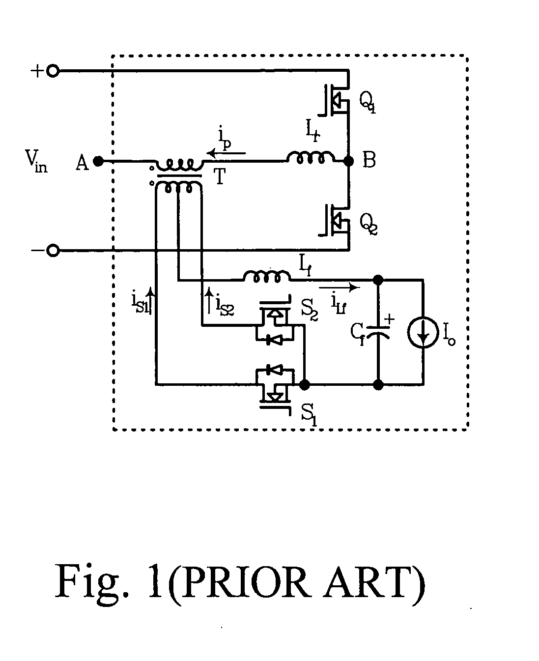
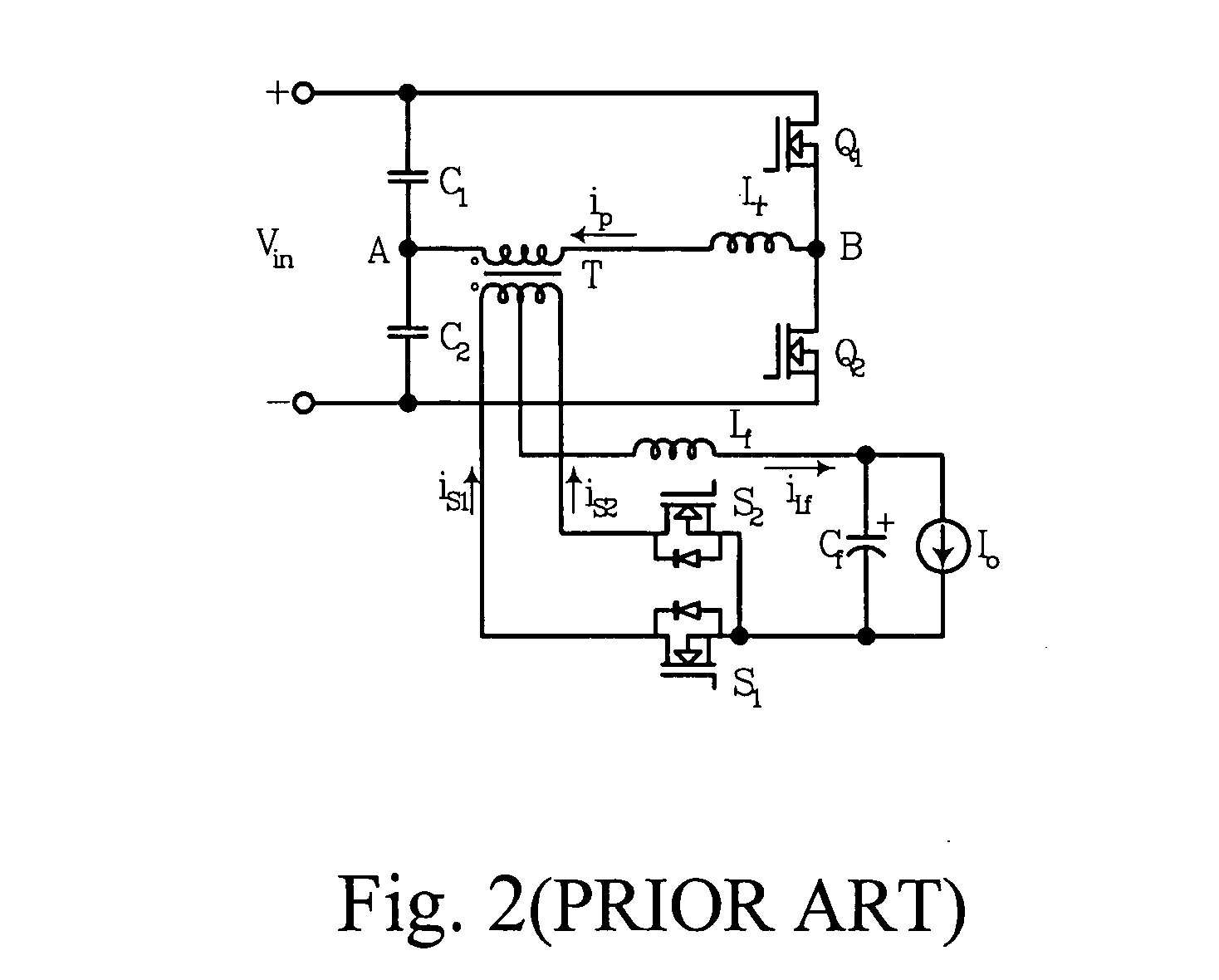
[0027]To facilitate the explanation of the detailed technique features of the prior art and the proposed driving method, it is necessary to analyze the key current and voltage variation after the turning off of the primary MOSFET. FIG. 10 shows the detailed timing diagram of the proposed control method, which is for the asymmetric controlled half bridge topology shown in FIG. 2.

[0028]Please refer to FIG. 2, the switching power converter includes an input voltage source Vin, a first switching device Q1 and a second switching device Q2, a transformer T, a rectifying circuit including a first synchronous rectifier S2 and a second sy...


PUM


Abstract

A control method for a first synchronous rectifier and a second synchronous rectifier in a switching power converter is presented. The switching power converter includes a transformer, and a first switching device and a second switching device connected in series and in parallel with an input voltage source. The first synchronous rectifier is connected with a low end of a secondary winding of the transformer. The second synchronous rectifier is connected with a high end of the secondary winding of said transformer. The first switching device is connected with a high end of the input voltage source, and the second switching device is connected with a low end of the input voltage source. The control includes the steps of driving the first switching device to an on state and the second switching device to an off state; and driving the second synchronous rectifier to an off state after the second switching device has been driven to an on state, such that a power is delivered from the primary winding to the secondary winding.

Description

FIELD OF THE INVENTION[0001]The present invention relates to switching power supplies and particularly to a method and circuit for controlling synchronous rectifiers used in ZVS DC / DC converter.BACKGROUND OF THE INVENTION[0002]As the same with most power supply products, the development trends of DC / DC converter is towards high efficiency, high power density, high reliability and, low cost. For a conventional ZVS DC / DC converter with the diode rectification, the conduction loss of the diode rectifier is normally about 30%–40% of the total loss of the converter. Obviously, in order to further improve the efficiency of the DC / DC converter, it is a good idea to reduce the conduction loss of the rectifier. Synchronous rectifier, which has the lower conduction loss, may be used in DC / DC converter. Although the employment of the synchronous rectifier can significantly reduce the conduction loss, the driver issue of the synchronous rectifier has to be considered.[0003]From the point of vie...

Claims


Application Information

Patent Timeline
Patent Type & Authority Patents(United States)
IPC IPC(8): H02M3/335
CPCH02M3/33592Y02B70/1475Y02B70/10
Inventor YAN, CHAOYE, HAO-YIWU, HONG-YANGZENG, JIAN-HONGYING, JIAN-PING
Owner DELTA ELECTRONICS INC
Why Eureka
Try Eureka