Grid that tracks the occurrence of a N-dimensional matrix of combinatorial events in a simulation using a linear index

Inactive Publication Date: 2006-08-29
APPLE INC
View PDF24 Cites 9 Cited by
  • Summary
  • Abstract
  • Description
  • Claims
  • Application Information

AI Technical Summary

Benefits of technology

[0023]The grid includes a monitor declaration that provides a unique name for the grid, n ordered axis declarations, wherein n is at least 1, that name a first through a nth axis, one or more logic expressions, and a grid declaration. Each axis declaration corresponds to a functional attribute of the design and lists two or more functional states of the functional attribute. The size of each axis comprises the number of functional states listed in its axis declaration. The logic expressions evaluate whether the design has achieved one of the functional states along each axis, and if a logic expression relating to an axis evaluates true, it sets the axis variable for that axis to the integer value corresponding to the functional state found. If all n axis variables are set to valid values during the evaluation of the logic expressions, the grid declaration converts the n axis variables to a unique linear index value that corresponds to the cross-product of the functional states achieved by the design, and records hits at each unique linear index value determined. The grid declaration can maintain a hit map indexed to the unique linear index for later downloading to a database.
[0024]The grid calculates the unique linear index value by multiplying the integer value of each axi

Problems solved by technology

In more complex designs, events may happen serially so that the number of states is increased.
Exhaustive verification of modern digital designs such as microprocessors is virtually impossible because such designs may attain an almost incalculable number of states.
In many cases, the random test generator ends up creating situations that a tester may not have thought to create.
One drawback to random test case generation is that it is difficult to know exactly what is being tested.
Consequently, it is difficult to gain an adequate level of confidence that the design is at

Method used


Image

  • Grid that tracks the occurrence of a N-dimensional matrix of combinatorial events in a simulation using a linear index
  • Grid that tracks the occurrence of a N-dimensional matrix of combinatorial events in a simulation using a linear index
  • Grid that tracks the occurrence of a N-dimensional matrix of combinatorial events in a simulation using a linear index

Examples


Embodiment Construction

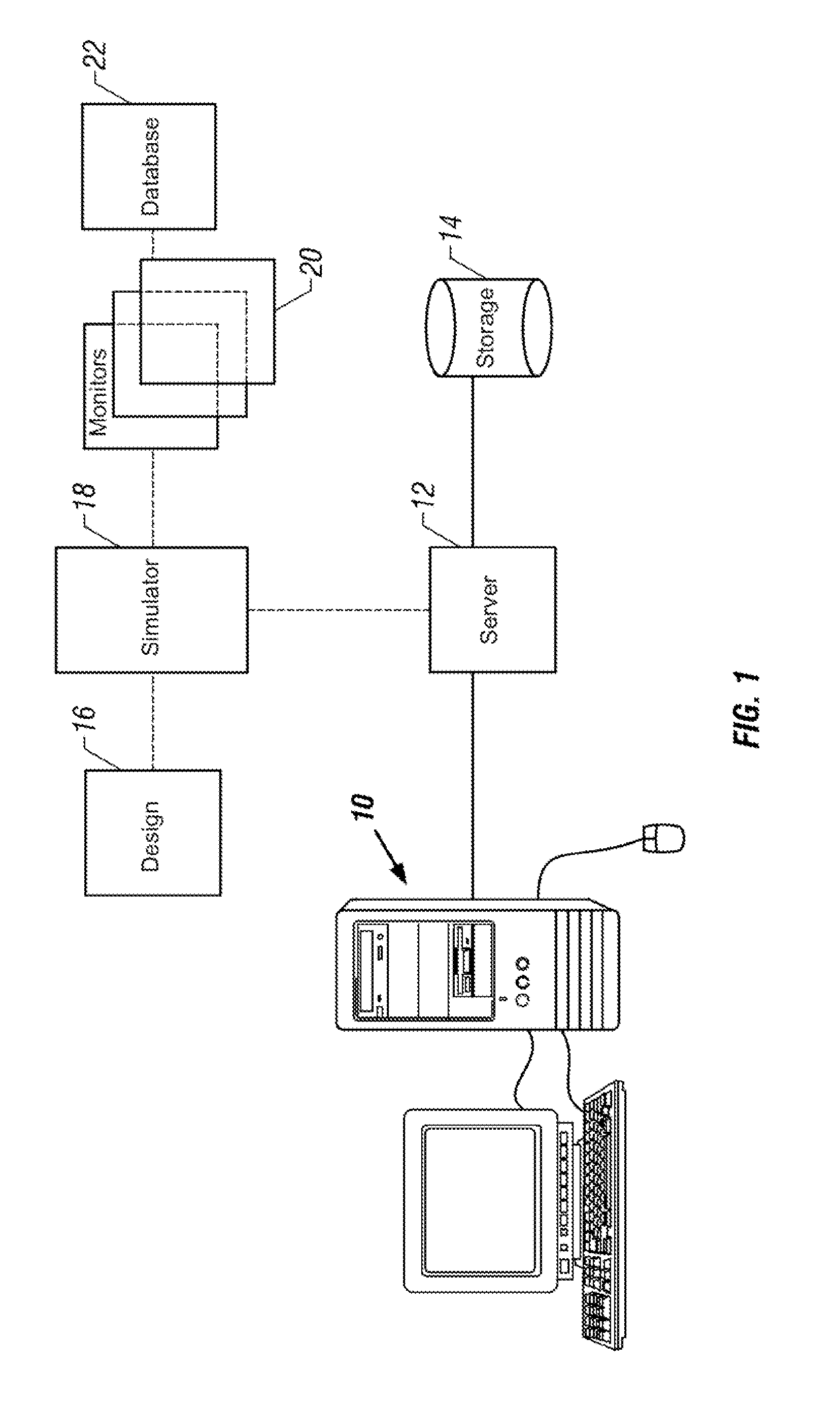
[0034]The present invention is a method and apparatus that monitors the simulation of a digital design such as a processor, and detects and reports certain events and combinations of events to a database. This disclosure describes numerous specific details that include specific software structures and example instruction streams in order to provide a thorough understanding of the present invention. One skilled in the art will appreciate that one may practice the present invention without these specific details.

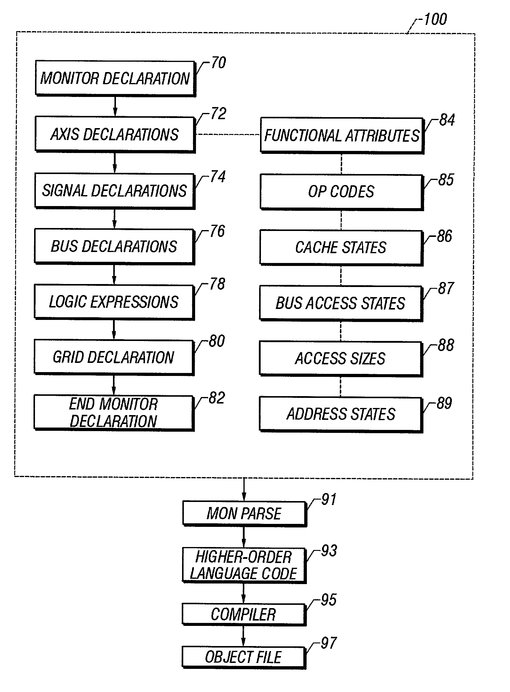
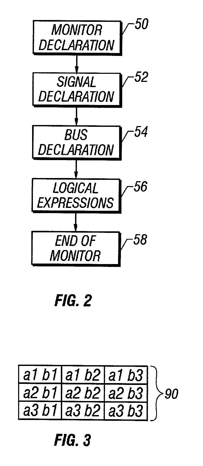
[0035]In the embodiment described herein, the present invention is implemented in a monitor language described in detail in the Monitor and Grid Patents. That description is not repeated here, and readers interested in the particulars of the monitor language are encouraged to refer to the Monitor and Grid Patents for the specific information they seek. As described in the Monitor and Grid Patents, the monitor language provides a straightforward method for a user to create a so...


PUM


Abstract

The disclosed invention is a grid that monitors a design simulation to support design verification coverage analysis. The disclosed invention includes n ordered axis declarations 72 that each correspond to a functional attribute and list at least two valid functional states, logic expressions 78 that test for the functional states and set axis variables, and a grid declaration 80 that converts the axis variables to a unique linear index value corresponding to the cross-product of the achieved functional states and records hits. The linear index is calculated by multiplying the integer value of each axis variable (except the nth axis variable) by the product of the sizes of each higher-order axis than the axis to which said axis variable corresponds, summing the results, and adding the integer value of the nth said axis variable.

Description

[0001]This application claims the benefits of the earlier filed U.S. Provisional Application Ser. No. 60 / 302,593, filed Jul. 2, 2001 (02.07.2001), which is incorporated by reference for all purposes into this specification.[0002]Additionally, this application is a continuation-in-part of U.S. patent application Ser. No. 09 / 406,016, filed 24 Sep. 1999 (24.09.1999), now U.S. Pat No. 6,594,803 entitled “Method and Apparatus that Reports Multiple Status Events with a Single Monitor”, which is incorporated by reference for all purposes into this specification and referred to herein as “the Grid Patent.”CROSS REFERENCE TO RELATED APPLICATIONS[0003]This application is related to U.S. patent application Ser. No. 09 / 406,017, filed 24 Sep. 1999 (24.09.1999), entitled “Method and Apparatus for a Monitor that Detects and Reports a Status Event to a Database”, which is incorporated by reference for all purposes into this specification and referred to herein as “the Monitor Patent.”BACKGROUND OF ...

Claims


Application Information

Patent Timeline
IPC IPC(8): G06F17/50G06F9/45G06G7/34G06F17/10
CPCG06F17/10
Inventor BOEHM, FRITZ A.
Owner APPLE INC
Why Eureka
Try Eureka