Concentric tube microplate autosample interface

a microplate and concentrate tube technology, applied in sampling, laboratory glassware, instruments, etc., can solve the problems of inability to chemically compatible tubes, tube made of a material capable of puncturing the seal covering the well, and tube made of stainless steel, etc., to achieve the effect of reducing the number of tubes

Active Publication Date: 2006-09-05
AGILENT TECH INC
View PDF11 Cites 21 Cited by
  • Summary
  • Abstract
  • Description
  • Claims
  • Application Information

AI Technical Summary

Benefits of technology

[0009]In related embodiments of the invention, the inner tube is mechanically biased in the transmission position, such bias being normally overcome while the outer tube is used to pierce the seal. In various embodiments, when the inner tube is in the transmission position, the tube assembly can be moved relative to the container so as to cause the end of the inner tube to make contact with the seal and move the inner tube into the piercing position. In various embodiments, when the inner tube is in the piercing position, the inner tube returns to the transmission position after the seal is pierced due to the mechanical bias. The inner tube may have a second end that is fixed in position relative to the outer tube, the inner tube being resilient so as to cause the inner tube to be mechanically biased in the transmission position. The second end of the inner tube may extend beyond the distal end of the outer tube, with a portion of the inner tube positioned between the distal end of the outer tube and the second end of the inner tube flexing when in the inner tube is in the piercing position. The inner tube may be capable of moving freely within the outer tube.

Problems solved by technology

However, problems arise when attempting to remove the sample from its respective well.
If the tube is too flexible, such as a tube made of Teflon, the tube will not be able to puncture the seal covering the well.
Alternatively, a tube made of a material capable of puncturing the seal, such as stainless steel, often is not chemically compatible.
When dealing with a large number of samples, the additional time required to thoroughly wash the stainless steel syringe, compared to a syringe made of a bio-inert substrate, can become a time consuming limitation on the system.
To minimize carry-over, various hydrophobic surface coatings may be applied to the surface of the syringe, however the durability of these surface coatings is limited.

Method used


Image

  • Concentric tube microplate autosample interface
  • Concentric tube microplate autosample interface
  • Concentric tube microplate autosample interface

Examples


Embodiment Construction

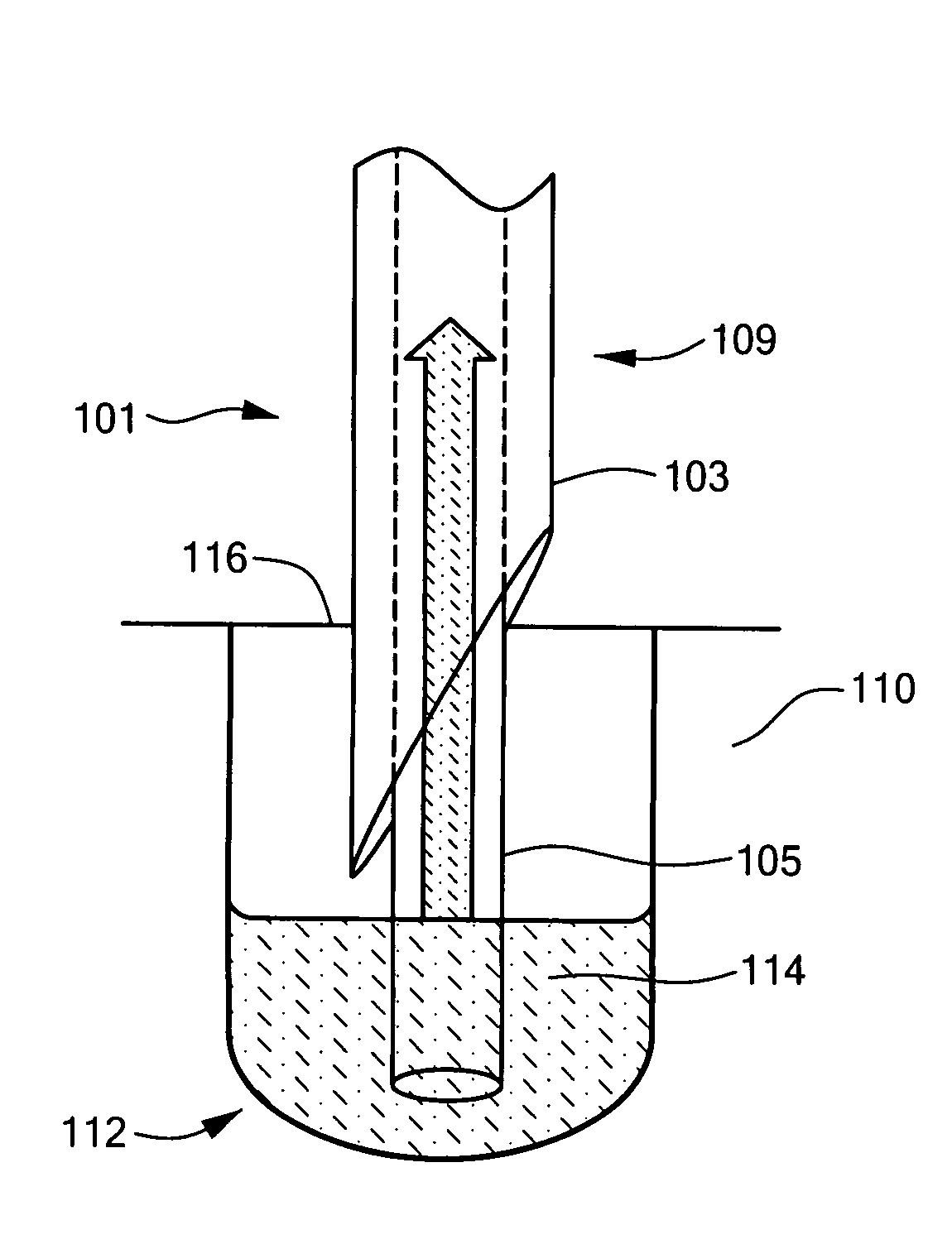
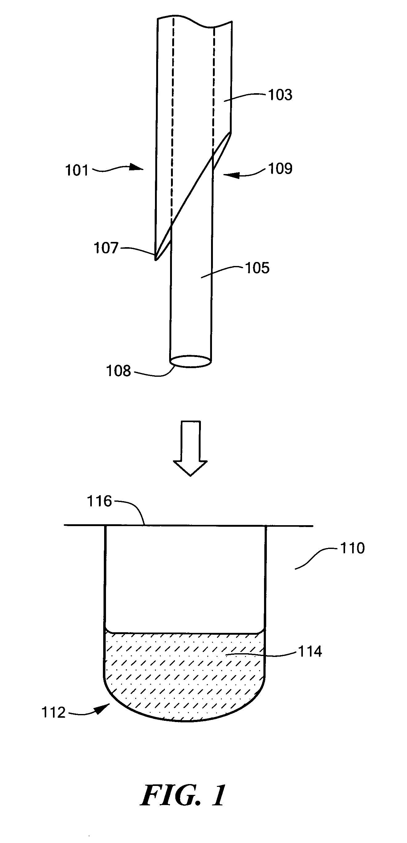
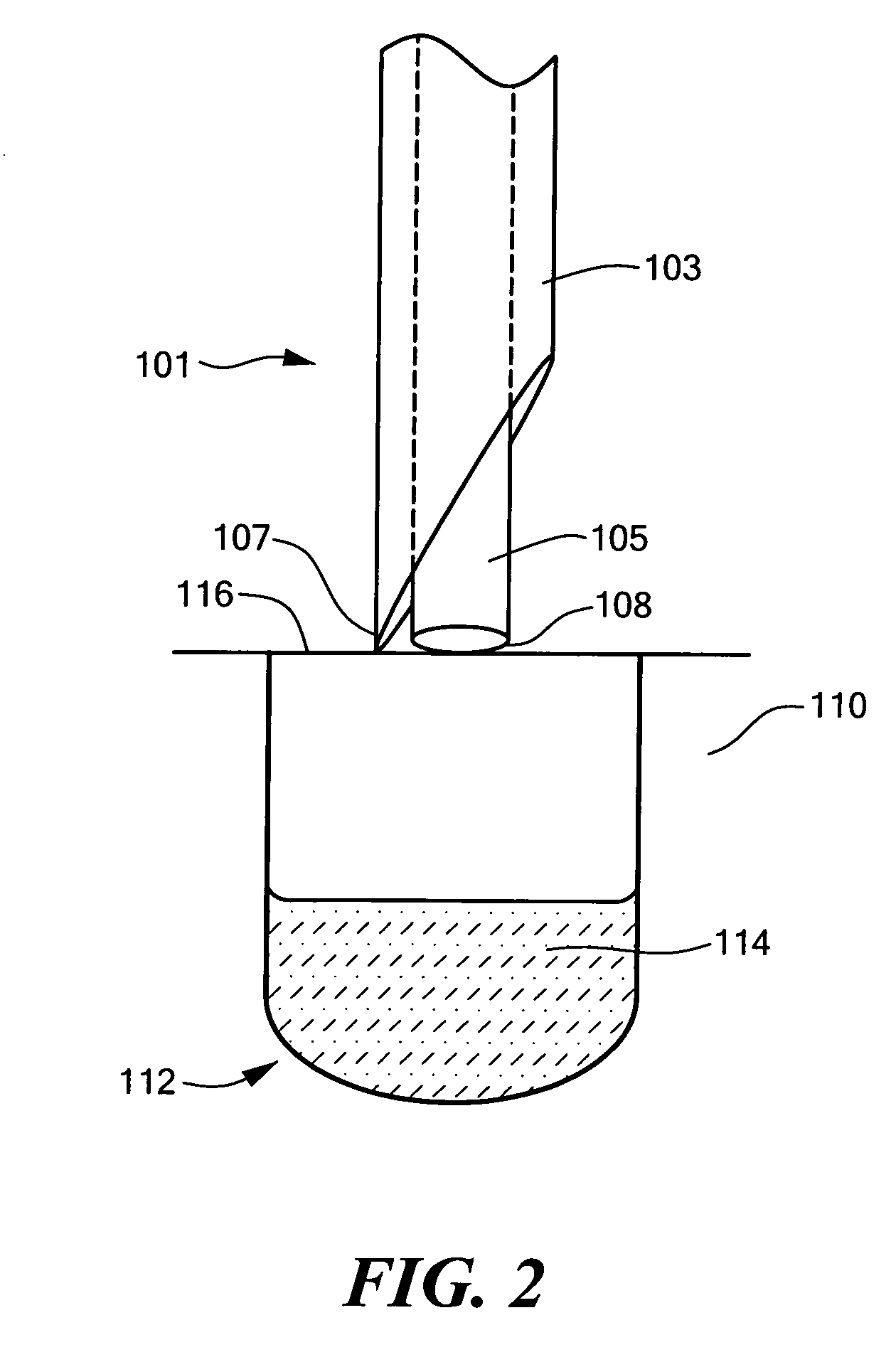
[0022]In illustrative embodiments, a system and method for transferring a sample from a volume closed by a seal is presented. Generally, the system includes a tube assembly having an outer tube and an inner tube. The inner tube includes an end region axially movable within the outer tube, such that the outer tube can be used to pierce the seal, while the inner tube can be used for contacting and transferring the sample from the volume. Consequently, the inner tube can advantageously have a small diameter and be made of a bio-inert substrate that, while not capable of piercing the seal, adsorbs very little sample. Sample carryover and the time required to wash the tubing prior to transfer of the next sample can thus be minimized. Details are discussed below.

[0023]FIG. 1 shows a tube assembly 101 approaching a container 110, in accordance with one embodiment of the invention. The container 110 defines at least one volume capable of containing a sample 114 to be aspirated. In various e...


PUM

PropertyMeasurementUnit
volumeaaaaaaaaaa
diameteraaaaaaaaaa
diameteraaaaaaaaaa

Abstract

In accordance with an illustrative embodiment of the invention, a system for obtaining a fluidic sample from a container is presented. The container defines a volume for holding the sample, the volume being closed by a seal. An outer tube has a proximal end and a distal end, the proximal end shaped to permit piercing the seal. An inner tube has an end region axially movable within the outer tube between a piercing position, wherein an end of the inner tube in the end region is retracted from the proximal end of the outer tube, and a transmission position, wherein the end of the inner tube extends axially beyond the proximal end of the outer tube. The outer tube and the inner tube form a tube assembly. At least one of the tube assembly and the container can be moved to cause the outer tube to pierce the seal and, after the seal is pierced, the inner tube can be used in the transmission position to permit fluid transfer with respect to the volume.

Description

TECHNICAL FIELD[0001]The invention generally relates to techniques for assaying sample liquids, and more specifically to physical transfer of a small sample of fluid from a sealed volume.BACKGROUND ART[0002]High-throughput screening (HTS) is a method for the rapid and accurate analysis of large numbers of chemical compounds for activity against selected targets. Typical chemical libraries contain hundreds of thousands to millions of separate compounds that are screened against a wide variety of targets. The large numbers of assays that must be routinely screened has led to a requirement for new technologies capable of rapid and quantitative analysis of small amounts of fluidic samples.[0003]Often, the small samples to be processed in HTS are initially stored in a plurality of small wells formed in a microplate. The microplate, which is typically made of polypropylene or other plastic, may vary in size, and include any number of wells. For example a standard microplate may have a dim...

Claims


Application Information

Patent Timeline
Patent Type & Authority Patents(United States)
IPC IPC(8): B01L3/02G01N1/00G01N35/10
CPCG01N35/1079
Inventor OZBAL, CAN
Owner AGILENT TECH INC
Why Eureka
Try Eureka