Shoring assembly and method

a technology of shoring assembly and assembly, which is applied in the direction of shaft equipment, shaft lining, artificial islands, etc., can solve the problems of uncontrolled movement, hazard to the operator carrying the shoring assembly, and uncontrolled dropping of the lower rail and pivoting of the hydraulic jack

Active Publication Date: 2006-09-05
CWS ROADPLATE LLC
View PDF18 Cites 8 Cited by
  • Summary
  • Abstract
  • Description
  • Claims
  • Application Information

AI Technical Summary

Benefits of technology

[0012]In one aspect, the present invention provides a shoring assembly, including a pair of rails, a plurality of first pads each having an end pivotally connected to one of the rails for pivotal movement between open and closed positions, a plurality of second pads each having an end pivotally connected to the other of the rails for pivotal movement between open and closed positions, and a plurality of hydraulic jacks each being operatively connec

Problems solved by technology

This creates a risk that the rails will separate (under the weight of the “lower” rail and the jack assembly) while being carried, resulting in uncontrolled dropping of the lower rail and pivoting o

Method used


Image

  • Shoring assembly and method
  • Shoring assembly and method
  • Shoring assembly and method

Examples


Embodiment Construction

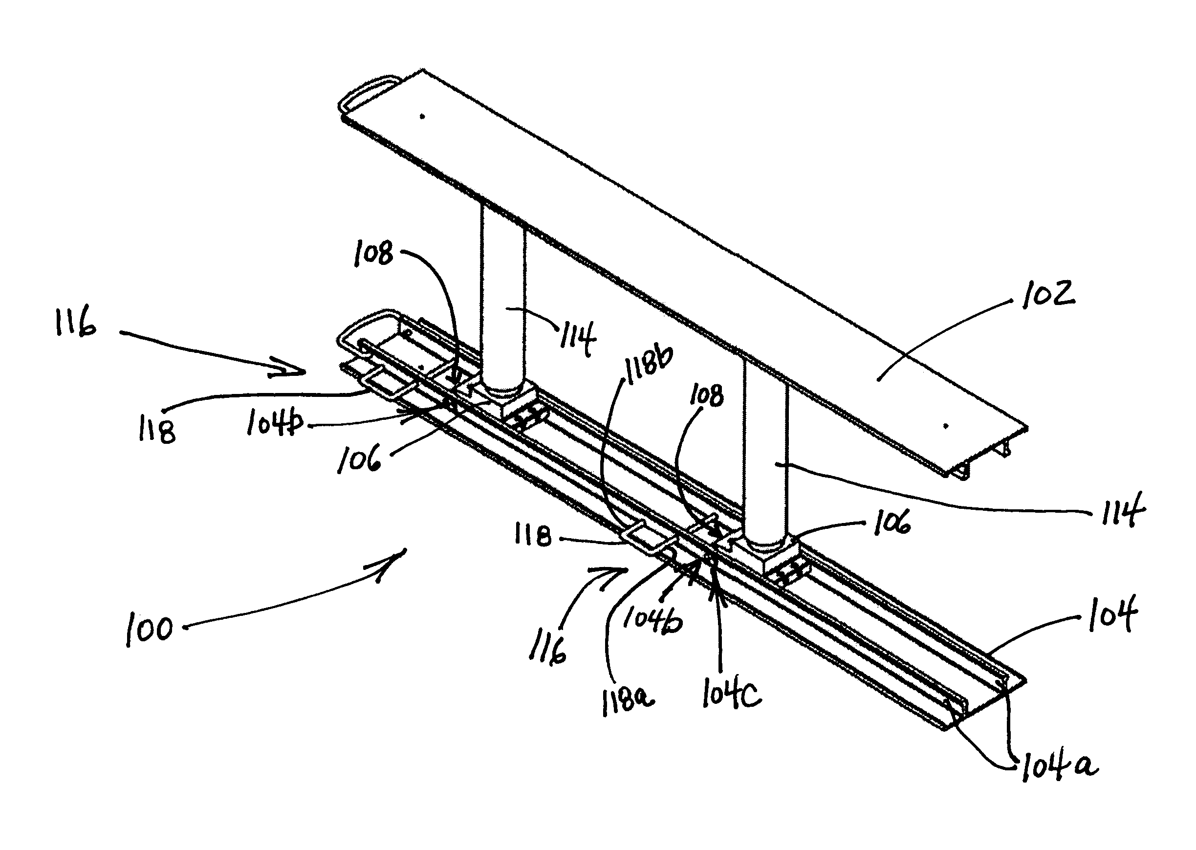
[0036]FIG. 4 illustrates one aspect of the present invention in the form of a shoring assembly 100. The shoring assembly 100 includes a pair of rails consisting of a cylinder rail 104 and a socket rail 102. The illustrated embodiment employs rails that are adapted for vertical shoring applications, and is commonly known in the art as a “vertical shore.” Alternatively, the rails may be adapted for horizontal shoring applications, in which case the rails are referred to in the art as walers.

[0037]A pair of first pads 106, called cylinder pads, each has an end 108 pivotally connected to the cylinder rail 104 for pivotal movement between open (or unfolded) and closed (or folded) positions. The open, unfolded position is shown in FIG. 4, while the closed, folded position is shown in FIG. 10 (described below).

[0038]FIGS. 7A–B illustrate a particular embodiment of the cylinder pad 106 in detail. The pad 106 includes a body 106a equipped with an upper face 106b having a threaded cylinder po...


PUM


Abstract

An inventive apparatus and method provides for restricting movement from a collapsed or folded position of a pair of rails employed by a shoring assembly. The shoring assembly has a plurality of first pads each pivotally connected to one of the rails, a plurality of second pads each pivotally connected to the other of the rails, and a plurality of hydraulic jacks each being operatively connected between an opposing pair of the first and second pads. The pivoting movement of the plurality of first pads is restricted relative to the one rail when the rails are disposed in the collapsed position. In a particular embodiment, a pair of first pads and a pair of second pads—respectively known as cylinder pads and socket pads—are employed by the shoring assembly. Accordingly, a pair of hydraulic jacks are further employed in this embodiment of the shoring assembly.

Description

BACKGROUND OF THE INVENTION[0001]1. Field of the Invention[0002]The present invention relates to shoring assemblies, such as vertical shoring assemblies, that support the sides of an excavation and which are designed to prevent cave-ins.[0003]2. Background of the Related Art[0004]It is common practice to shore or support the walls of an excavation (i.e., a trench) with one or more shoring systems. It is well known in the art of shoring to employ collapsible hydraulic shoring systems which are adapted for repeated use. FIG. 1 depicts a plurality of typical shoring systems 10, commonly known in the art as a vertical shores, used in parallel to support the walls W of an excavation. Each of the shoring systems includes a pair of aluminum rails (also known in the art as uprights) 12 suitable for abutting the walls W of the excavation and providing the support desired. The rails 12 are shown spaced apart by a pair of hydraulic jacks (also known in the art as crossbraces) 14 which are pivo...

Claims


Application Information

Patent Timeline
IPC IPC(8): E02D17/04
CPCE02D17/08
Inventor CERDA, VICTOR M
Owner CWS ROADPLATE LLC
Why Eureka
Try Eureka