Computer interface system for tracking of radio frequency identification tags

a computer interface and radio frequency identification technology, applied in the direction of testing/monitoring control systems, instruments, program control, etc., can solve the problems of inability to apply the prior art's tracking technology to changing areas, inability to provide a method for tracking where powered transceivers are impractical, etc., to facilitate the selection of phone conversations

Active Publication Date: 2006-09-05
GLOBAL TELLINK
View PDF6 Cites 189 Cited by
  • Summary
  • Abstract
  • Description
  • Claims
  • Application Information

AI Technical Summary

Problems solved by technology

The prior art fails to provide for tracking where large numbers of radio frequency (rf) signals are tracked within human populations.
It also does not provide a method for tracking where powered transceivers are impractical over large areas.
There is also a failure of the prior art to apply the technology of tracking to changing areas, tracking typically being done is static environments.

Method used


Image

  • Computer interface system for tracking of radio frequency identification tags
  • Computer interface system for tracking of radio frequency identification tags
  • Computer interface system for tracking of radio frequency identification tags

Examples


Embodiment Construction

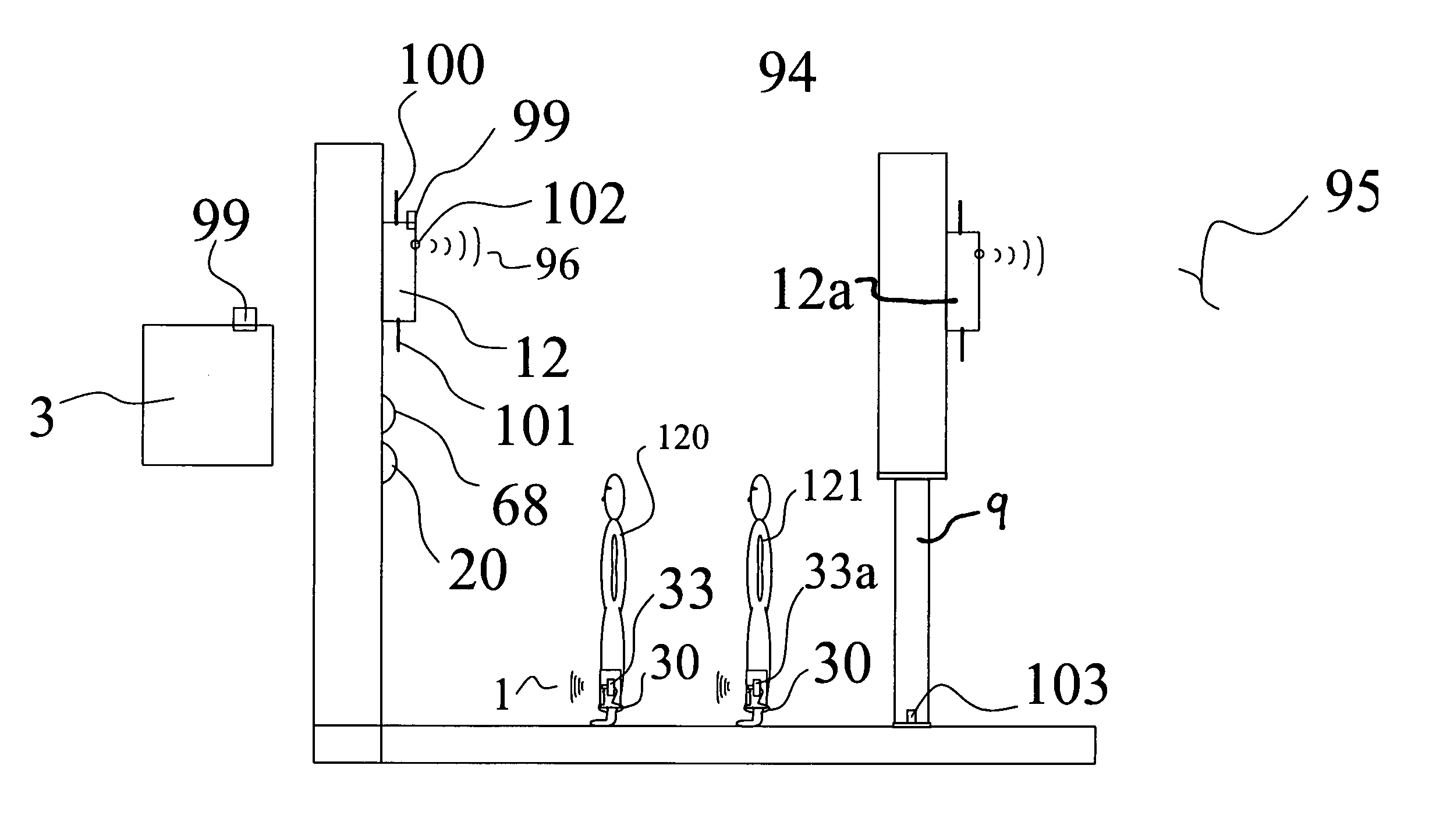
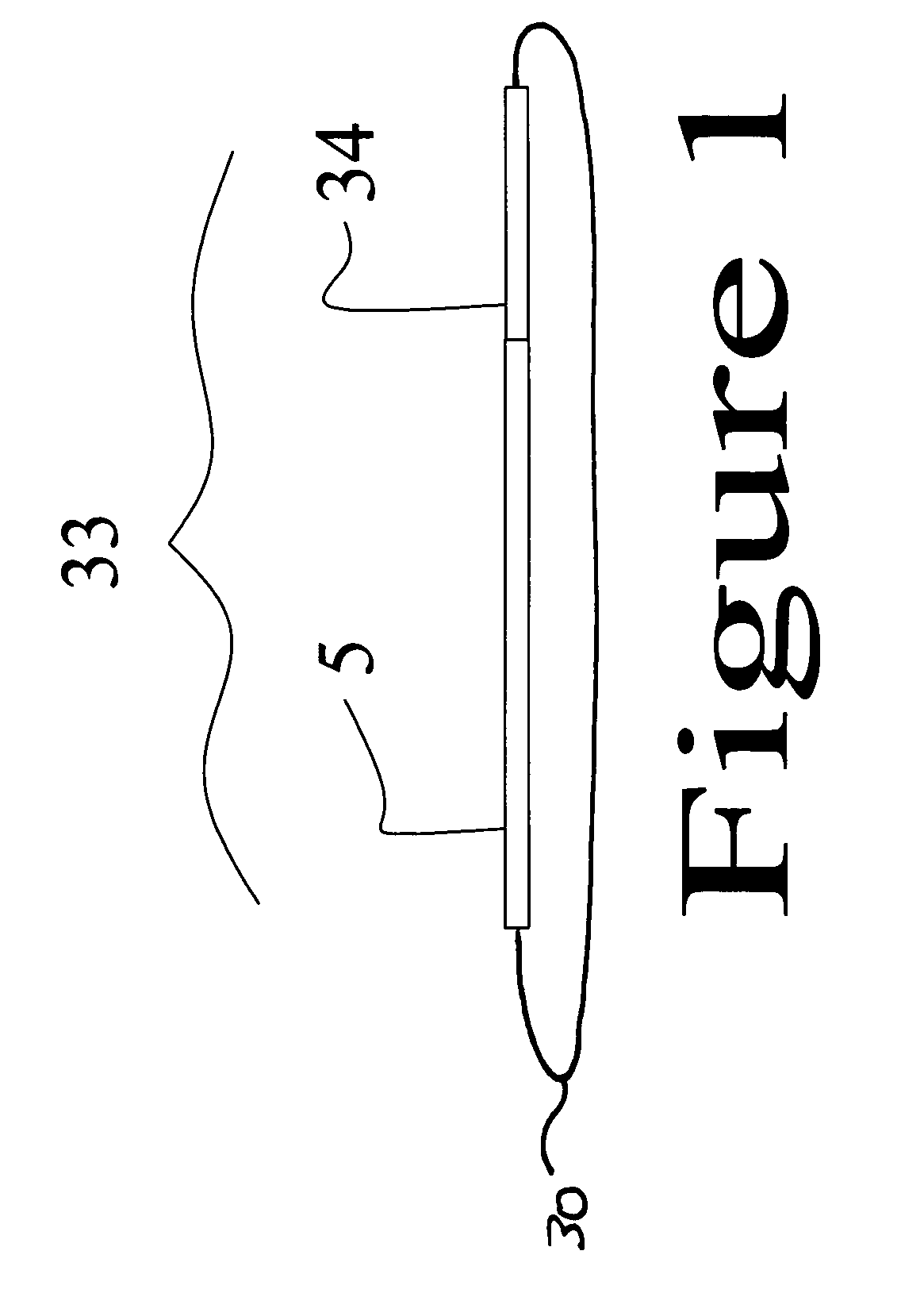
[0055]As can best be seen by reference to FIG. 1, an actual passive device 33 used in the preferred embodiment is nearly flat and less than 1 inch square. The device size allows it to be integrated into almost anything. It consists of a micro transceiver 5 and an antennae 34 of a type known in the prior art since they are not powered, they rely on a pulse from a transmitter on a transceiver 12 to generate power for a response signal.

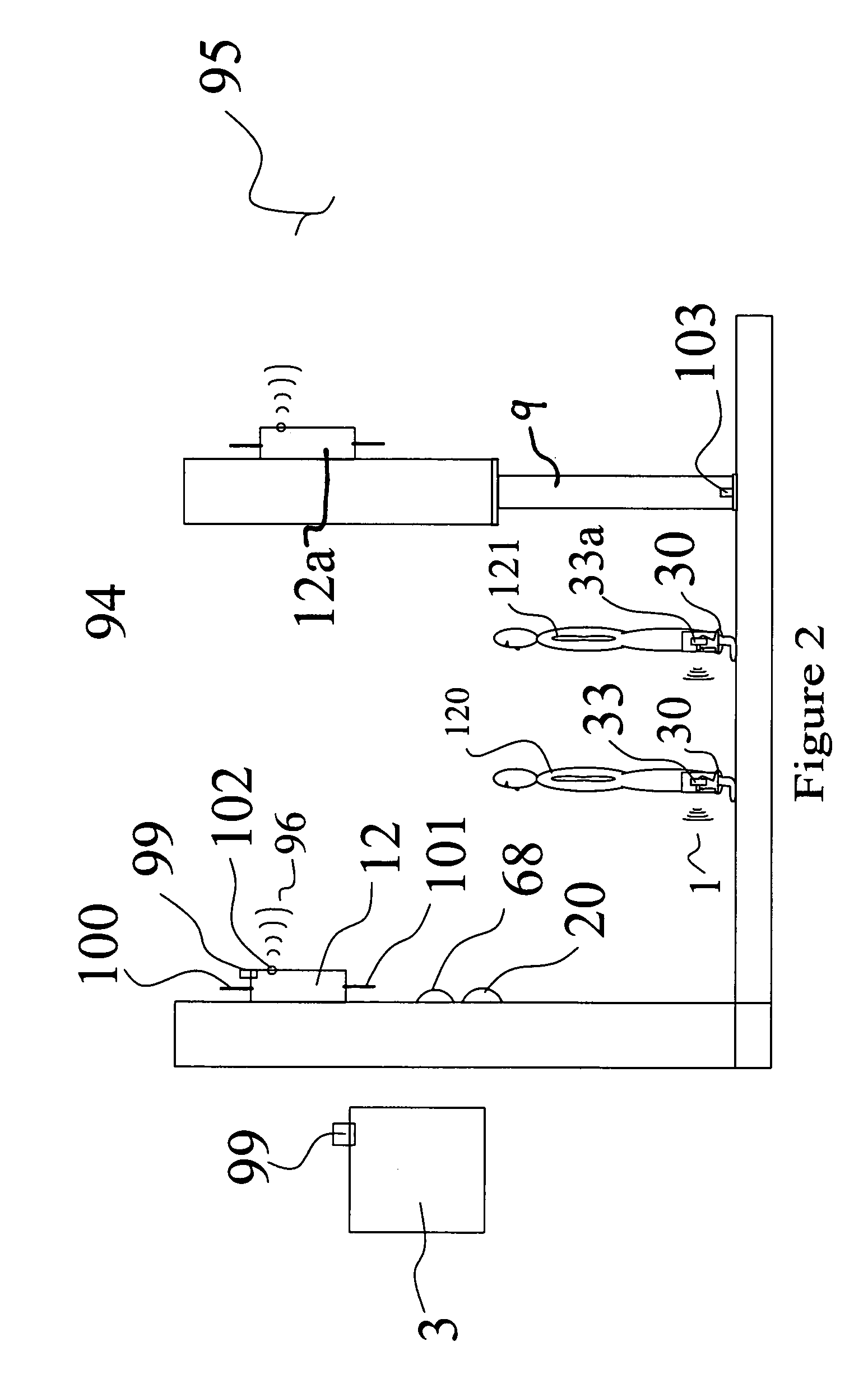
[0056]FIG. 2 shows a possible transceivers-passive device 33 antenna solutions that tracks appropriately tuned passive devices. The passive devices can be mounted discretely and hidden to the point to where they are almost undetectable. They can, for example, be run in the seams of clothing. In FIG. 2 they are shown as a bracelet around the ankle although a hospital wrist type bracelet would work as well.

[0057]This invention has the following general parameters:

[0058]a) use of passive transmitters to track objects within defined spaces;

[0059]b) modified ...


PUM


Abstract

A method for operating with multiple protocols for handling communications comprising the steps of obtaining information from sensors and related input devices utilizing specialized tamper resistant passive transceivers working with active pulse type transceivers to create historical maps of information on people or objects. This includes steps of: a) identifying recording information, b) sending and receiving prompts, c) associating the call with timers, d) monitoring passive transceivers with low level diagnostic information, e) monitoring the transceivers with voice recognition software, f) recording associated data, g) identifying the users, the key words or phrases within the recorded data, h) naming the recording and i) saving the data in a protected format.

Description

PRIORITY STATEMENT[0001]Patent claims priority of provisional patent no.:60 / 439,777 filed Jan. 11, 2003.BACKGROUND OF INVENTION[0002]1. Prior Art[0003]Prior art shows the use of RFID (Radio Frequency Identification) tags utilized extensively in the prior art and in conjunction with monitoring devices over various areas.[0004]Maloney; U.S. Pat. No. 6,427,913, shows the use of RFID tags on keys in order to monitor the use of keys over a predetermined area.[0005]Examples of the use of this technology are fairly widespread including Curkendell, et al, U.S. Pat. No. 6,342,839 which shows the use of RFID tags retracting livestock and includes the storage of data in order to maintain the data which is consistent with the method taught in Maloney whereby information can be stored in order to determine authorized and unauthorized use.[0006]Pruett; U.S. Pat. No. 6,263,440 shows the use of this technology for tracking computers.[0007]Blackenship et al; U.S. Pat. No. 6,267,291 shows the use of ...

Claims


Application Information

Patent Timeline
Patent Type & Authority Patents(United States)
IPC IPC(8): G08B1/08H04Q7/00
CPCG06Q10/08
Inventor ANDERS, JOSEPHBIRCH, JEREMYWILSON, BRYANLOGSDON, MARTY
Owner GLOBAL TELLINK
Why Eureka
Try Eureka