
Communication device using an UWB wireless wave

a communication device and wireless wave technology, applied in the field of communication devices using uwb wireless wave, can solve problems such as difficulties in application to typical radar systems or communication systems, and achieve the effect of precise and reliable detection of objects

Inactive Publication Date: 2006-09-05
FUJITSU COMPONENENT LTD
View PDF13 Cites 13 Cited by
  • Summary
  • Abstract
  • Description
  • Claims
  • Application Information

AI Technical Summary

Benefits of technology

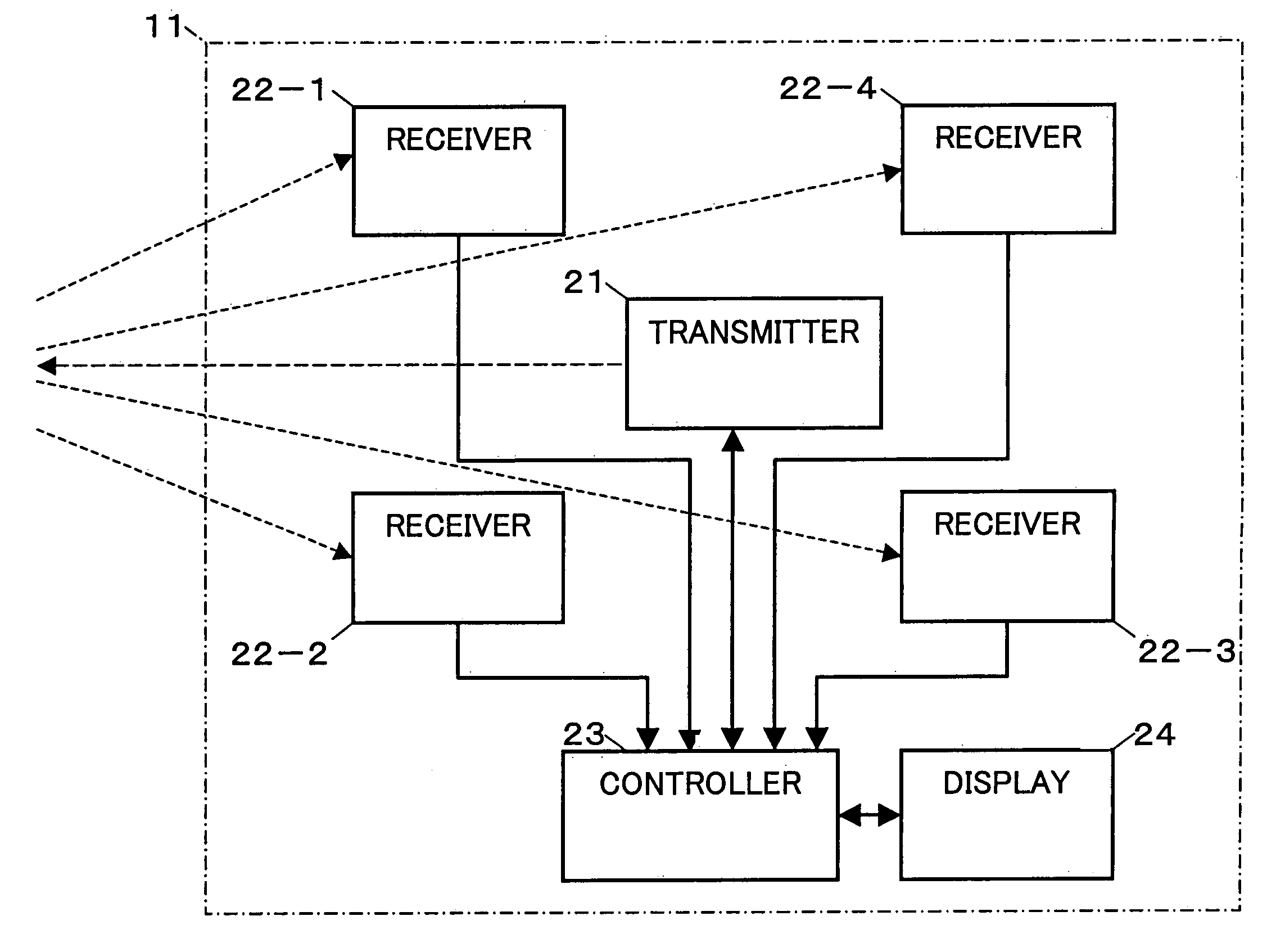
The present invention is a communication system that uses UWB communication to detect objects near a detector. The system includes a detector, a communication device, and an interface for interfacing with a user. The detector transmits an ultra wide band wireless wave pulse and the communication device communicates with the detector using UWB communication. The system can measure the distance and direction of an object based on the time interval between the transmission and reception of the ultra wide band wireless wave pulse. The invention also provides a distance-measuring system for measuring the distance and direction of an object using UWB communication. Additionally, the invention provides a communication method for sharing information among multiple moving objects equipped with communication devices in a predetermined area. The use of ultra wide band communication allows for precise and reliable detection of objects located in close proximity.

Problems solved by technology

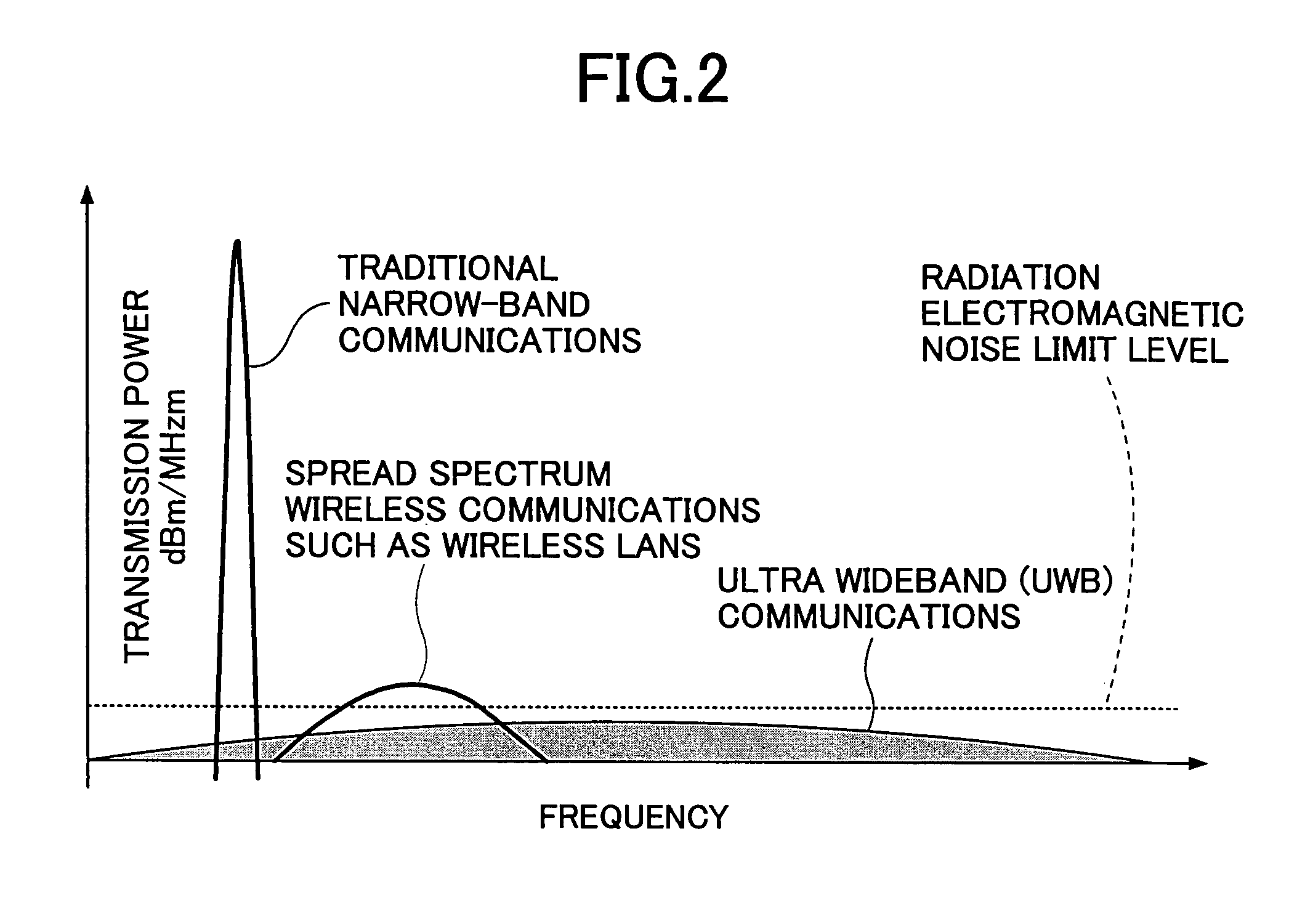
However, since the transmit power is restrained up to a radiation electromagnetic noise limit level in the UWB system, as shown in FIG. 2, there has been no other choice but to shorten the communication distance.
However, since the communication distance is short, application to typical radar system or communication system involves difficulties.

Method used


Image

  • Communication device using an UWB wireless wave
  • Communication device using an UWB wireless wave
  • Communication device using an UWB wireless wave

Examples


Embodiment Construction

[0036]FIG. 3 shows an embodiment of a system configuration according to the present invention. In this system configuration, on a vehicle 1 are installed vehicle-installed devices such as an ultra wide band (UWB) communication system 11, a radar system 12, an audiovisual system 13, a navigation system 14, a monitoring system 15, a control system 16, and so on.

[0037]The UWB communication system 11 is a system that utilizes an ultra wide band wireless wave pulse (hereafter “UWB wireless wave pulse”) to implement various functions such as a distance-measuring function, an inter-vehicle communication function, an anti-theft function, etc.

[0038]The radar system 12 is the system that detects an obstacle ahead of the vehicle using a radar wave.

[0039]The audiovisual system 13 is a system for playing an audiovisual content, which includes an audio system for playing a music CD such as a CD player and a visual system such as a television monitor.

[0040]The navigation system 14 is a system that...


PUM


Abstract

A communication device is disclosed which is comprised of: a transmitter for transmitting an ultra wide band wireless wave pulse; multiple receivers which are disposed equidistant from the transmitter and receive the ultra wide band wireless wave pulse; and distance-measuring equipment which detects a distance or a direction to an object by measuring time intervals between the first reception times when receivers receive the ultra wide band wireless wave pulse directly from the transmitter and the second reception times when the receivers receive a object-reflected wave of the ultra wide band wireless wave pulse.

Description

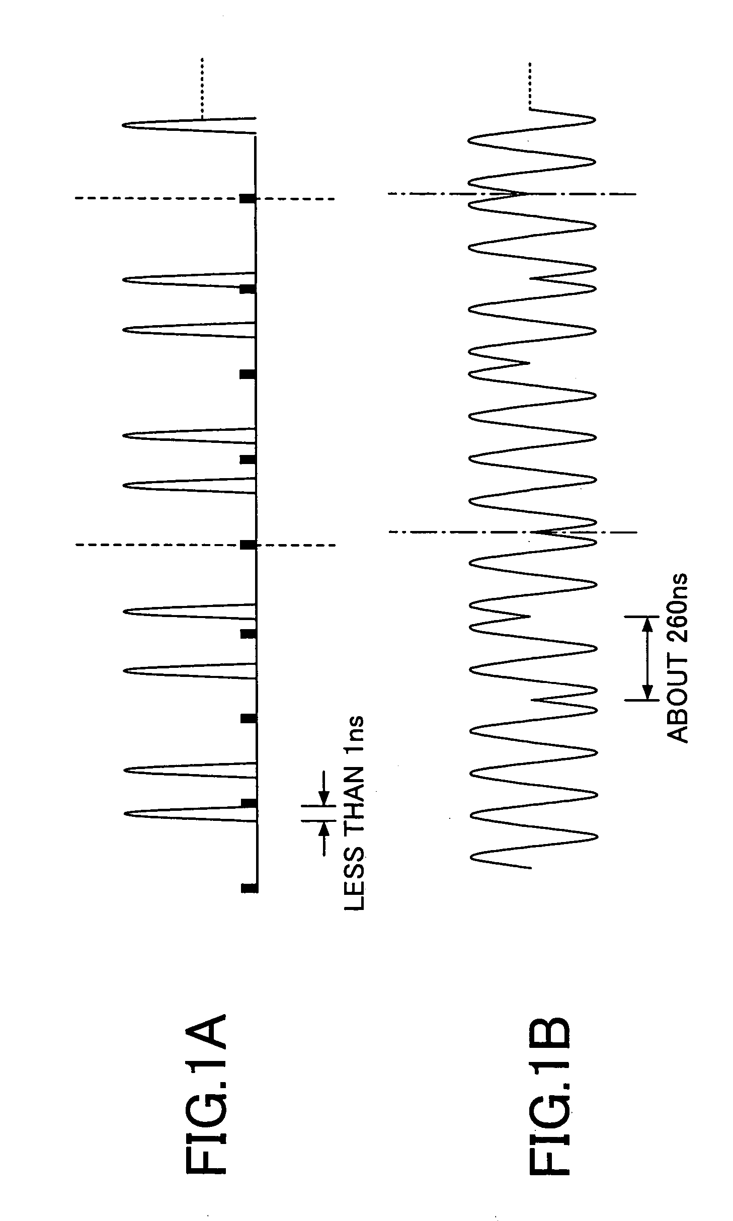
BACKGROUND OF THE INVENTION[0001]1. Field of the Invention[0002]The present invention relates to a communication device, a vehicle-installed system, a communication system, and an anti-theft system, in particular to the same that utilize an ultra wide band (UWB) wireless wave.[0003]2. Description of the Related Art[0004]A UWB wireless system is a wireless system in which communication is carried out by using significantly wide-range frequency-band and narrow pulses of about several GHz or several tens of GHz and less than 1 ns.[0005]FIG. 1 shows a wave shape of transmitted data of the wireless communication system and FIG. 2 shows a frequency band of the wireless communication system. FIG. 1B illustrates the wave shape of PSK (phase sift keying) and FIG. 1A illustrates the wave shape of UWB.[0006]Communication is carried out by generating a narrow-wide pulse, called as an impulse, in a data train that is less than 1 ns. Since the UWB system can avoid the necessity for continuously g...

Claims


Application Information

Patent Timeline
Patent Type & Authority Patents(United States)
IPC IPC(8): G08G1/16B60R16/023B60R25/00B60R25/31G01S3/50G01S13/02G01S13/10G01S13/74G01S13/86G01S13/93G08B13/183
CPCG01S3/50G01S13/867G01S2013/936G01S13/0209G01S2013/9316
Inventor INOUE, HIROTOARITA, TAKASHI
Owner FUJITSU COMPONENENT LTD
Learn More