Zoom lens system and image pickup device having zoom lens system

a technology of zoom lens and image pickup device, which is applied in the field of zoom lens system, can solve the problems of difficult to obtain preferable optical performance over the entire zoom range, difficult to correct astigmatism, and large aberration variation of zooming, and achieves wide field angle and high optical performance.

Active Publication Date: 2006-09-05
CANON KK
View PDF27 Cites 13 Cited by
  • Summary
  • Abstract
  • Description
  • Claims
  • Application Information

AI Technical Summary

Benefits of technology

[0010]The present invention has been made in view of the above-mentioned circumstances in the conventional zoom lens. An object of the present invention is to provide a small size zoom lens system having high optical performance over an entire zoom range with a wide field angle.

Problems solved by technology

However, when the refractive power of each of the lens units is merely increased, a variation in aberration with zooming becomes larger.
In particular, when a wide field angle is to be obtained, it is hard to obtain preferable optical performance over the entire zoom range.
When an ultra wide field angle is set, it is hard to correct astigmatism.
Therefore, there has been such a tendency that high performance cannot be obtained or a size of the zoom lens increases.

Method used


Image

  • Zoom lens system and image pickup device having zoom lens system
  • Zoom lens system and image pickup device having zoom lens system
  • Zoom lens system and image pickup device having zoom lens system

Examples


Embodiment Construction

[0028]Hereinafter, a zoom lens system and an image pickup device having the zoom lens system according to an embodiment of the present invention will be described with reference to the drawings.

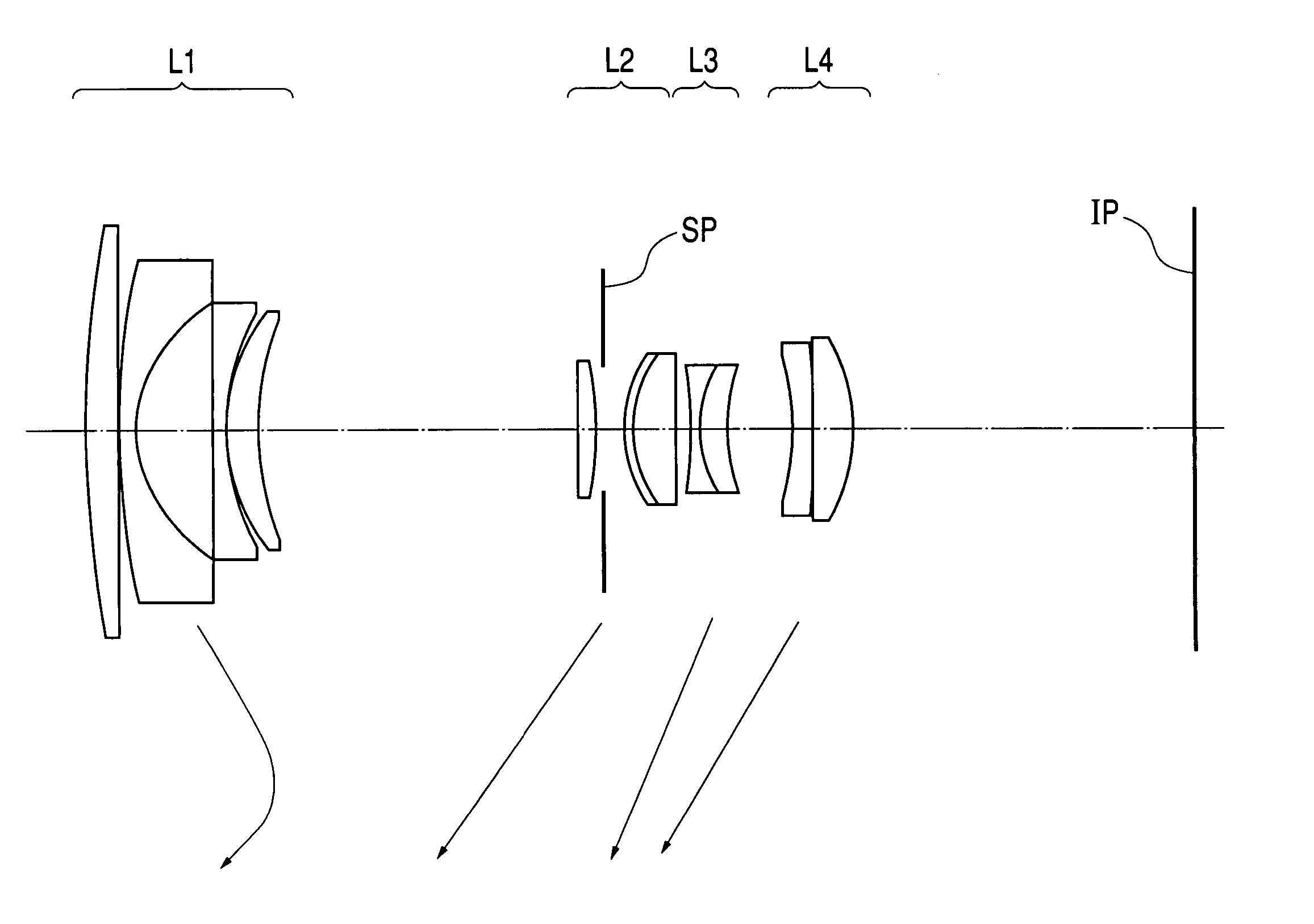
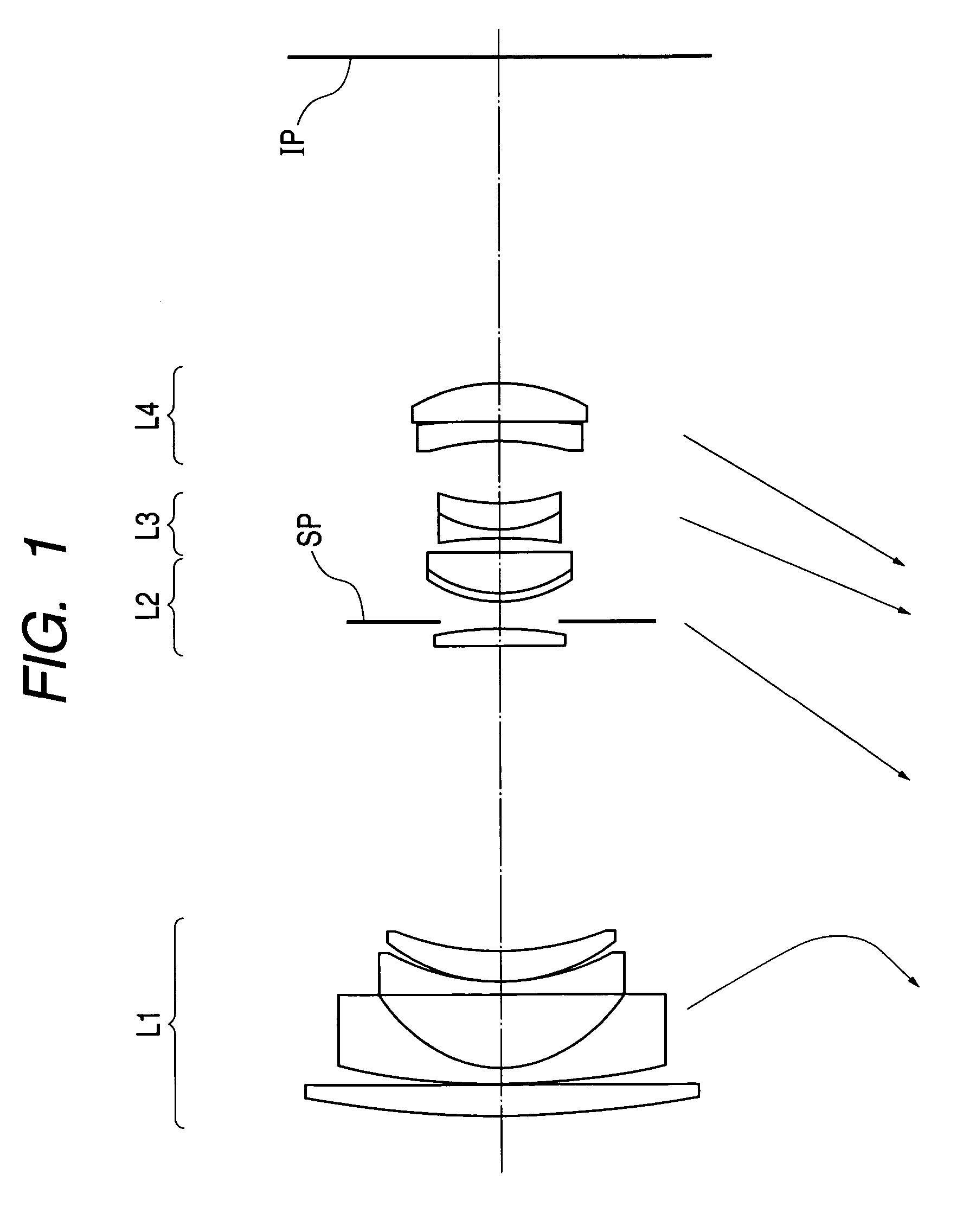
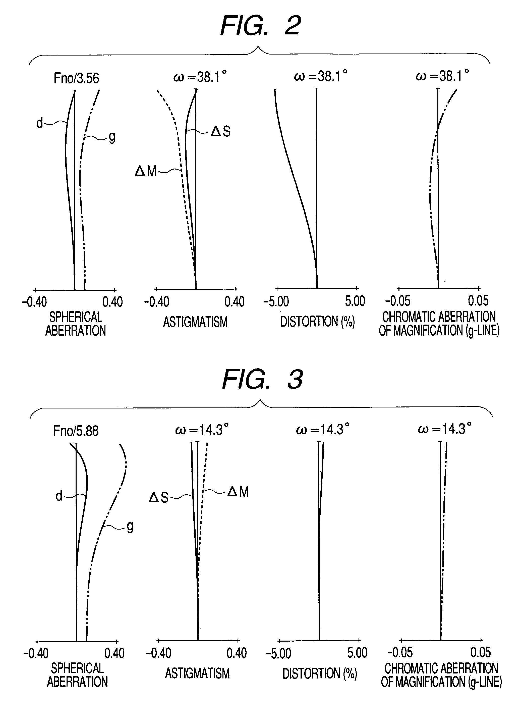
[0029]FIGS. 1, 4, 7, 10, and 13 are lens sectional views showing a zoom lens at a wide angle end, according to Numerical Embodiments 1 to 5 (hereinafter collectively called “this embodiment”) described later, respectively. FIGS. 2 and 3 are various aberration graphs of the zoom lens at wide angle end and telephoto end according to Numerical Embodiment 1. FIGS. 5 and 6 are various aberration graphs of the zoom lens at wide angle end and telephoto end according to Numerical Embodiment 2. FIGS. 8 and 9 are various aberration graphs of the zoom lens at wide angle end and telephoto end according to Numerical Embodiment 3. FIGS. 11 and 12 are various aberration graphs of the zoom lens at wide angle end and telephoto end according to Numerical Embodiment 4. FIGS. 14 and 15 are various aberration gra...


PUM


Abstract

To realize a zoom lens system, including, in order from an object side to an image side: a first lens unit having a negative optical power; a second lens unit having a positive optical power; a third lens unit having a negative optical power; and a fourth lens unit having a positive optical power, in which: during zooming, an interval between the first lens unit and the second lens unit at a telephoto end is smaller than that at a wide angle end, an interval between the second lens unit and the third lens unit at the telephoto end is larger than that at the wide angle end, and an interval between the third lens unit and the fourth lens unit at the telephoto end is smaller than that at the wide angle end; and specific conditions are satified.

Description

BACKGROUND OF THE INVENTION[0001]1. Field of the Invention[0002]The present invention relates to a zoom lens system, and more particularly to a zoom lens system suitable for a silver halide film camera, an electronic recording type digital still camera, an electronic recording type video camera, or the like.[0003]2. Related Background Art[0004]A so-called negative lead type zoom lens, in which a lens unit having a negative refractive power, is disposed on its front side has been used for a wide angle zoom lens in many cases, since it has characteristics of: “a distance for close-up image pickup is relatively short”, “a field angle can be relatively easily widened”, “a back focus can be relatively easily lengthened”, and the, like.[0005]On the other hand, in the negative lead type zoom lens, at a telephoto end, a first and a second lens units consist a positive group and a third and a fourth lens units consist a negative group, so that the entire optical system can be used as a so-ca...

Claims


Application Information

Patent Timeline
Patent Type & Authority Patents(United States)
IPC IPC(8): G02B15/14G02B15/20G02B13/18G02B15/177
CPCG02B15/177G02B15/144511
Inventor NISHIMURA, TAKESHI
Owner CANON KK
Why Eureka
Try Eureka