Door system with a pair of door panels connected by a swivel panel that swings back and forth for selectively opening and closing gateways in a compartment

a door panel and gate system technology, applied in the field of door systems, can solve the problems of heavy traffic of passersby through the compartment, the failure of conventional automatic door systems to achieve the effect of complete draught elimination, and the situation where both entrance doors and exit doors are opened, etc., and achieve the effect of low cos

Inactive Publication Date: 2006-09-12
NABCO LTD
View PDF17 Cites 17 Cited by
  • Summary
  • Abstract
  • Description
  • Claims
  • Application Information

AI Technical Summary

Benefits of technology

[0009]In view of the above problems residing in the prior art, an object of the invention is to provide a door system that enables to secure draught eliminating effect at a low cost.
[0012]On the way of swinging in the other direction, the door panels close the first and second gateways, respectively, and the compartment comes into another state where the compartment is separated into two sections by the swivel panel, and communication between the two sections is blocked by the swivel panel. While the compartment is in this state, communication between the indoor and the outdoor in the compartment is also blocked, and a passerby is allowed to pass a passage defined by the swivel panel and an inner surface of the compartment with draught eliminating effect being secured.

Problems solved by technology

However, in a case that a passerby is about to come into the compartment through the entrance door (exit door), and almost at the same timing, another passerby who is on the way of passing the compartment is about to go out of the compartment through the exit door (entrance door), or traffic of passersby through the compartment is heavy, it is highly likely that a situation where both of the entrance door and the exit door are opened may occur.
Thus, the conventional automatic door system fails to accomplish complete draught eliminating effect.
This may raise the production cost and running cost of the door system.
However, the revolving door system requires a relatively large space and requires signal communication between the door panels by slip rings, which raises the production cost and running cost of the door system.

Method used


Image

  • Door system with a pair of door panels connected by a swivel panel that swings back and forth for selectively opening and closing gateways in a compartment
  • Door system with a pair of door panels connected by a swivel panel that swings back and forth for selectively opening and closing gateways in a compartment
  • Door system with a pair of door panels connected by a swivel panel that swings back and forth for selectively opening and closing gateways in a compartment

Examples


Embodiment Construction

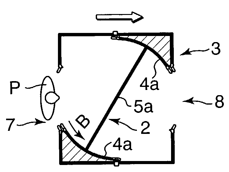
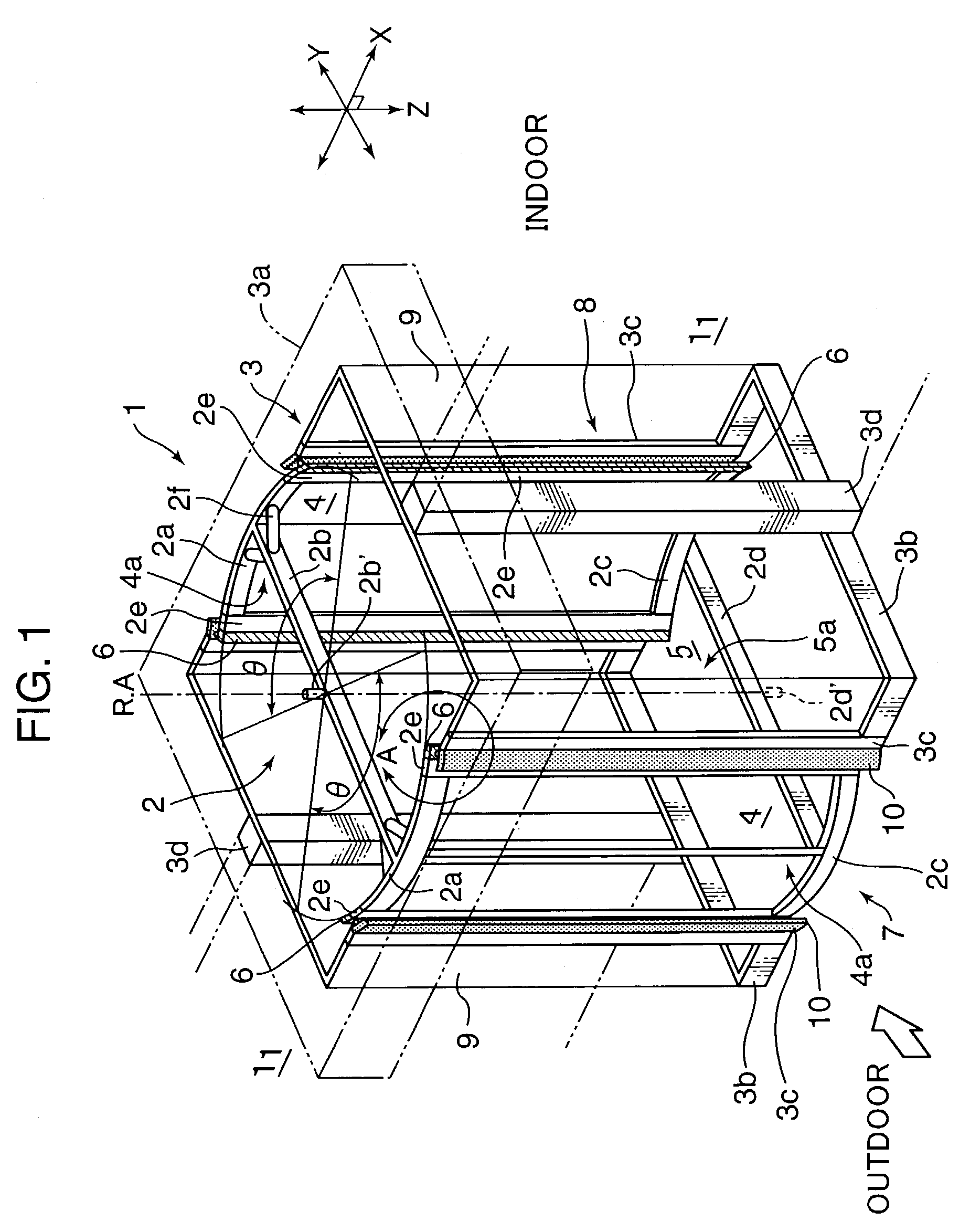
[0030]Referring to FIG. 1, a door system 1 incorporates a swivel panel unit 2 and a compartment 3 for housing the swivel panel unit 2 therein. The swivel panel unit 2 swings around an axis of rotation R.A. clockwise and counterclockwise alternately at an angular displacement of Θ (≦180°). The swivel panel unit 2 and a driving mechanism, which will be described later, constitute a barrier apparatus.

[0031]At an upper part of the swivel panel unit 2, provided are a pair of upper outer frames 2a, 2a each in the form of an arc in plan view, and an upper joint frame 2b with opposite longitudinal ends thereof being jointed to a middle part of the respective upper outer frames 2a, 2a. The upper outer frames 2a, 2a, and the upper joint frame 2b are assembled into a generally H-shape in plan view.

[0032]Similar to the upper part of the swivel panel unit 2, there are provided, at a lower part of the swivel panel unit 2, a pair of lower outer frames 2c, 2c each in the form of an arc in plan view...


PUM


Abstract

A door system has a compartment formed with a first gateway and a second gateway opposed to the first gateway, and a barrier apparatus housed in the compartment. The barrier apparatus includes a swivel panel which swings back and forth between a first position where one surface of the swivel panel faces the first gateway, and a second position where the opposite surface of the swivel panel faces the first gateway. The barrier apparatus further includes a pair of door panels provided at the opposite ends of the swivel panel to move with the swivel panel. The door panels synchronously open the gateways when the swivel panel is at the first position and at the second position. Air sealing is provided between the compartment and the door panels.

Description

BACKGROUND OF THE INVENTION[0001]1. Field of the Invention[0002]This invention relates to a door system with draught eliminating effect for use in an entrance / exit of a building.[0003]2. Description of the Related Art[0004]Heretofore, there is known an automatic sliding door provided at an entrance / exit of a building such as office buildings and public buildings. Such an automatic sliding door is provided to keep an air-conditioned state inside the building and / or to prevent draught from coming inside the building.[0005]In the conventional automatic door system, for example, a box shaped compartment is defined in an entrance zone of a building, an entrance and an exit are defined in positions opposing to each other of the compartment, and a pair of automatic sliding doors are provided on the entrance and the exit, respectively. Each of the automatic doors is individually controlled in such a manner that the door is opened each time a passerby passes the compartment.[0006]In the abov...

Claims


Application Information

Patent Timeline
Patent Type & Authority Patents(United States)
IPC IPC(8): E05D15/02E05F15/10E05F15/12E06B3/90
CPCE06B3/90E05F15/608E06B3/906E05Y2900/132E05F15/611
Inventor YOKOTACHI, HIROYUKI
Owner NABCO LTD
Why Eureka
Try Eureka