Roll stand

a technology of rolling stand and rolling plate, which is applied in the field of rolling plate, can solve the problems of difficult disassembly of the back-up, difficulty in practical application of quickly exchange, time-consuming, etc., and achieve the effect of carrying out more quickly and easily

Inactive Publication Date: 2006-09-12
SUNDWIG
View PDF18 Cites 10 Cited by
  • Summary
  • Abstract
  • Description
  • Claims
  • Application Information

AI Technical Summary

Benefits of technology

[0007]It is thus the object of the invention to improve a roll stand of the type explained above, such that chan

Problems solved by technology

However, with the known roll stand it has been shown to be difficult in practical application to quickly exchange for example a support roll or one of the back-up rolls, because this always necessitates extensive installation work.
This roll stand known from AT 359 459 is associated with the problem of disa

Method used


Image

  • Roll stand
  • Roll stand
  • Roll stand

Examples


Embodiment Construction

[0025]In the figures, elements with the same function have the same reference characters.

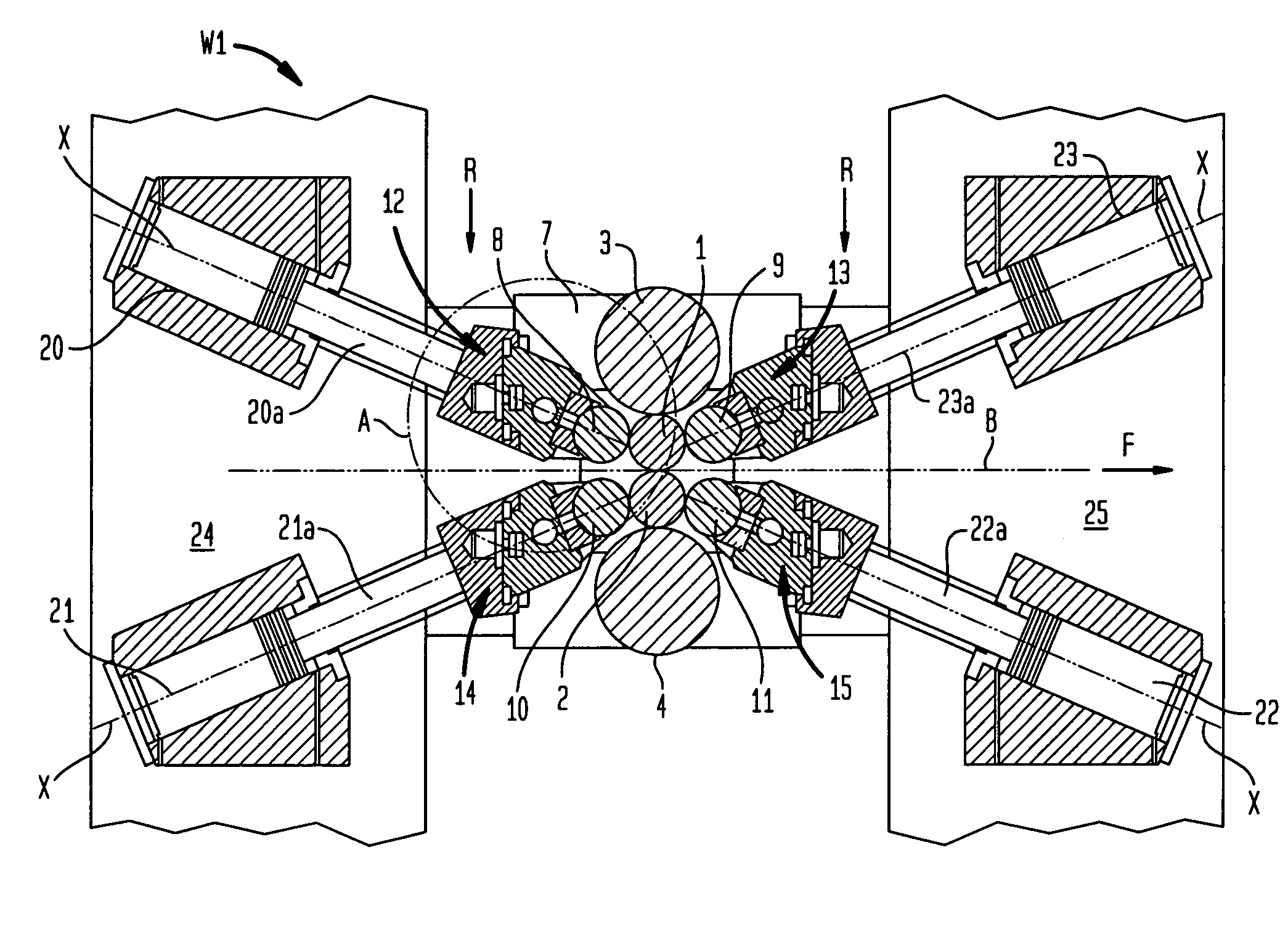
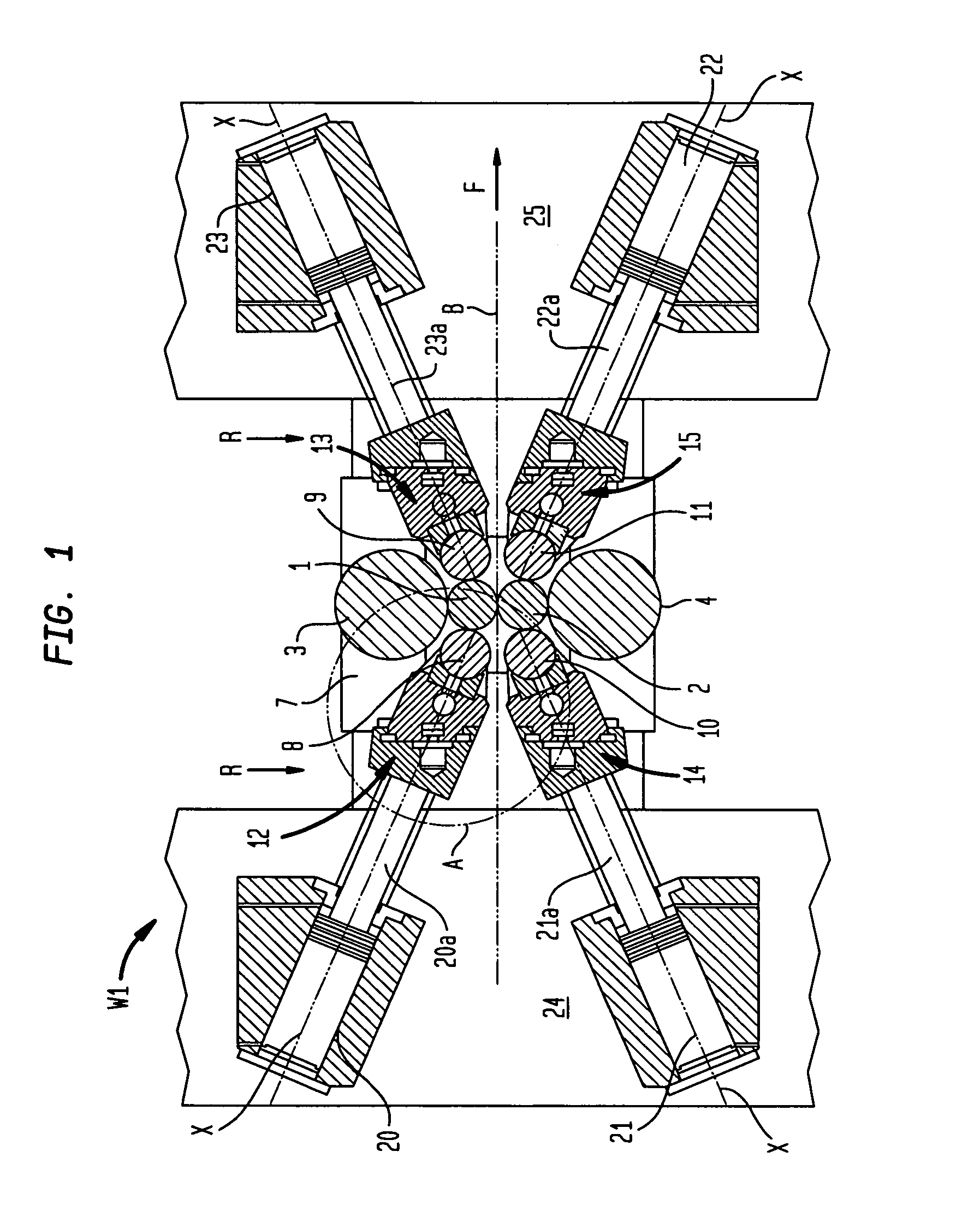
[0026]Each of the roll stands W1, W2 has two work rolls 1, 2. In vertical direction each work roll 1, 2 is supported by an intermediate roll 3, 4 against a support roll (not shown) whose axis of rotation is in the same plane as the axes of rotation of the work rolls 1, 2 and the intermediate rolls 3, 4. The intermediate rolls 3, 4 are held in a chock 7 and the support rolls (not shown) are held in a chock of their own (also not shown), while the work rolls 1, 2 are loosely held in the roll stand W1, W2. Between the work rolls 1, 2 there is a roll gap W in which a metal strip B, conveyed in the direction of conveyance F, is cold rolled.

[0027]The chock 7 is slidably held on a slideway (not shown); said chock can be withdrawn from the respective roll stand W1, W2 along its longitudinal direction, parallel to the axes of rotation of the work rolls, intermediate rolls and support rolls.

[0028]Each wor...


PUM

PropertyMeasurementUnit
Forceaaaaaaaaaa

Abstract

The invention relates to a roll stand comprising a pair of work rolls 1, 2 for rolling a metal strip B, comprising back-up rolls 8, 9, 10, 11 which provide lateral support to their respectively allocated work rolls 1, 2, with support force directed towards the work rolls 1, 2 being able to be applied to said back-up rolls by means of a force generation device, and comprising support rolls or intermediate rolls 3, 4 which are borne by a chock which can be slid into the roll stand W1, W2 in the direction of the longitudinal axis of said chock 7, and wherein said chock can be withdrawn from said roll stand, with each support roll or intermediate roll supporting an associated work roll 1, 2 in a direction which is essentially perpendicular to the direction of movement of the metal strip B. In such a roll stand, changing of the rolls can be carried out more quickly and easily in that the back-up rolls 8, 9, 10, 11 can be positioned from an idle position in which they are arranged outside the region where the chock 7 of the support roll or intermediate roll 3, 4 moves during slide-in or withdrawal, to an operating position in which they rest against the work roll 1, 2.

Description

BACKGROUND OF THE INVENTION[0001]The invention relates to a roll stand with a pair of work rolls for rolling a metal strip, comprising back-up rolls which provide lateral support to their respectively allocated work rolls, with support force directed towards the work rolls being able to be applied to said back-up rolls by means of a force generation device, and comprising support rolls or intermediate rolls which are borne by a chock, which can be slid into said roll stand in the direction of the longitudinal axis of said chock and wherein said chock can be withdrawn from the roll stand, with each support roll or intermediate roll supporting an associated work roll in a direction which is essentially perpendicular to the direction of movement of the metal strip.[0002]In a roll stand known from DE 29 19 105 C2, each of the work rolls is supported on a support roll via an intermediate roll. At the same time, two back-up rolls are associated with each work roll, with said back-up rolls...

Claims


Application Information

Patent Timeline
IPC IPC(8): B21B13/14B21B29/00B21B31/02F16C13/00B21B31/08F16C13/06
CPCB21B13/145B21B31/08
Inventor BERGER, BERNDSCHULTE, HEINRICHCOPPICUS, DAMIAN
Owner SUNDWIG
Why Eureka
Try Eureka