Normally open hydraulic control valve

a hydraulic control valve, normally open technology, applied in the direction of valve operating means/releasing devices, mechanical equipment, transportation and packaging, etc., can solve the problems of delay in the operation of the damper oil chamber, lack of rapidness, and supply of oil, and achieve the effect of convenient machin

Inactive Publication Date: 2006-09-12
KEIHIN CORP
View PDF11 Cites 38 Cited by
  • Summary
  • Abstract
  • Description
  • Claims
  • Application Information

AI Technical Summary

Benefits of technology

[0006]The present invention has been achieved in view of the above circumstances, and has an object to provide a normally open hydraulic control valve which suffers no restriction on placement of an oil tank, which is capable of quickly supplying oil to a damper oil chamber at the early stage of the operation, and which does not cause a delay in operation of the damper oil chamber.
[0019]With the first feature of the present invention, the supply port is normally opened, and therefore when the hydraulic pump is operated, the generated hydraulic pressure is immediately supplied to the reaction force oil chamber, and positively leaked and supplied to the adjacent damper oil chamber via the slide gap between the third land portion and the valve body. Accordingly, the damper oil chamber can be filled with oil without a delay from the early stage of the operation of the hydraulic control valve, and therefore the damper oil chamber can always exhibit a good vibration suppressing function for the spool. In addition, it is not necessary to submerge the damper chamber in the oil of the oil tank as in the prior art, and therefore there is no restriction on placement in the normally open hydraulic control valve, thus enhancing general versatility.
[0020]With the second feature of the present invention, the slide gap between the third land portion and the valve body is comparatively large. Therefore, even when the third land portion is moved sideways by receiving side thrust due to the leak oil passing through the slide gap, the aligning means receives the hydraulic pressure of the reaction force oil chamber and gives the aligning force to the third land portion, thereby ensuring smooth slide of the third land portion to the valve body.
[0023]With the fifth feature of the present invention, the first to the third land portions are all given the aligning force by the hydraulic pressure, thereby ensuring smooth slide of the spool to the valve body.
[0025]With the seventh feature of the present invention, even when the land portion is moved sideways by side thrust, the reduced diameter cylindrical surface receives the hydraulic pressure on its entire surface without contacting the inner peripheral surface of the valve body, thereby giving the aligning force to the land portion. Accordingly, the aligning means can be constructed by such an extremely simple structure that the reduced diameter cylindrical surface is provided on the outer peripheral surface of the land portion. In addition, this reduced diameter cylindrical surface is easier to be machined than the taper surface.

Problems solved by technology

In addition, the difference in level between the oil in the oil tank and the damper oil chamber is comparatively small, and therefore supply of the oil from the oil tank to the damper oil chamber by utilizing the difference lacks swiftness, thus causing a fear that a delay in operation of the damper oil chamber occurs at the early stage of the operation of the normally open hydraulic control valve.

Method used


Image

  • Normally open hydraulic control valve
  • Normally open hydraulic control valve
  • Normally open hydraulic control valve

Examples


first embodiment

[0035]the present invention shown in FIG. 1 to FIG. 4 will be explained.

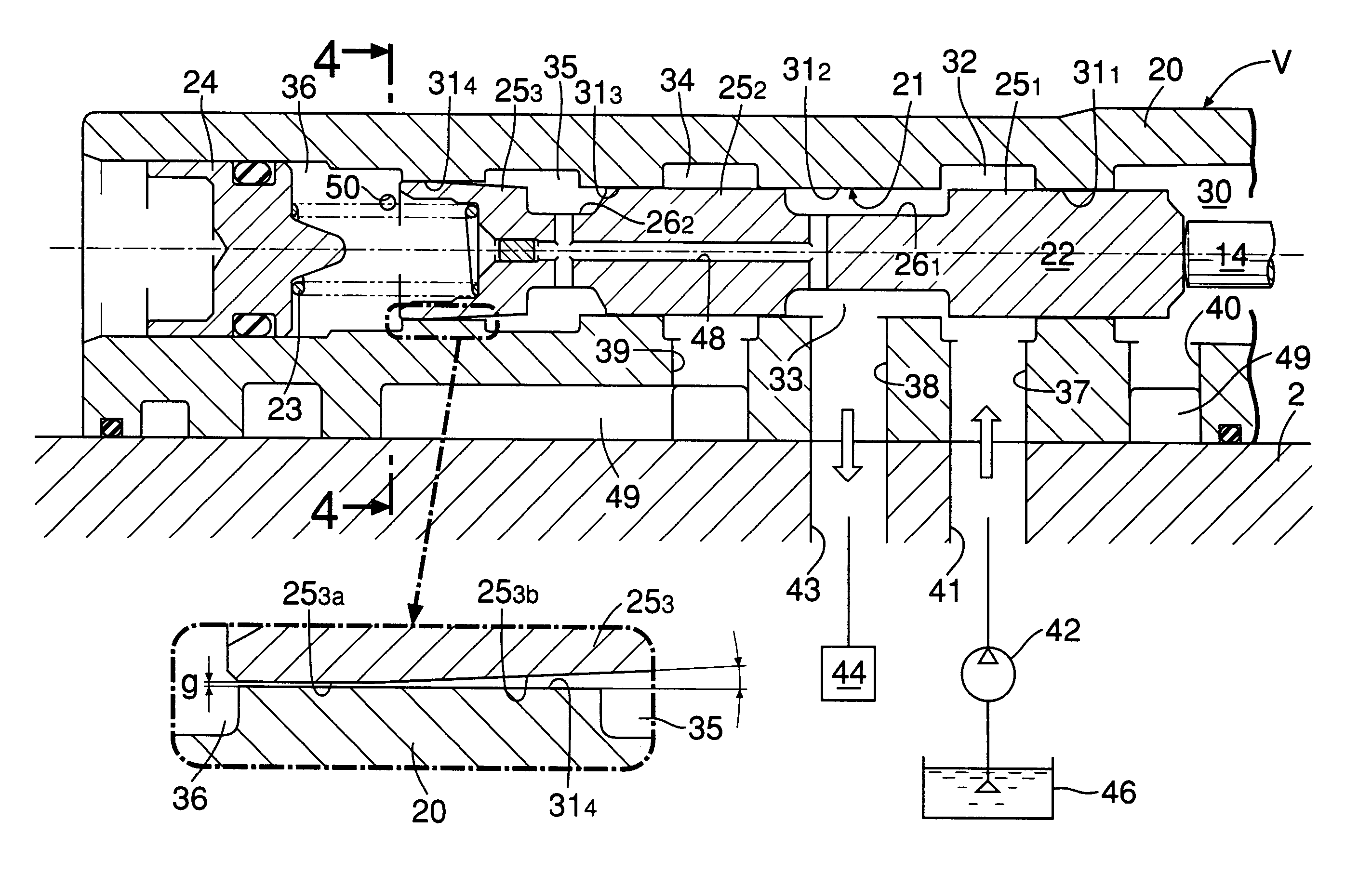
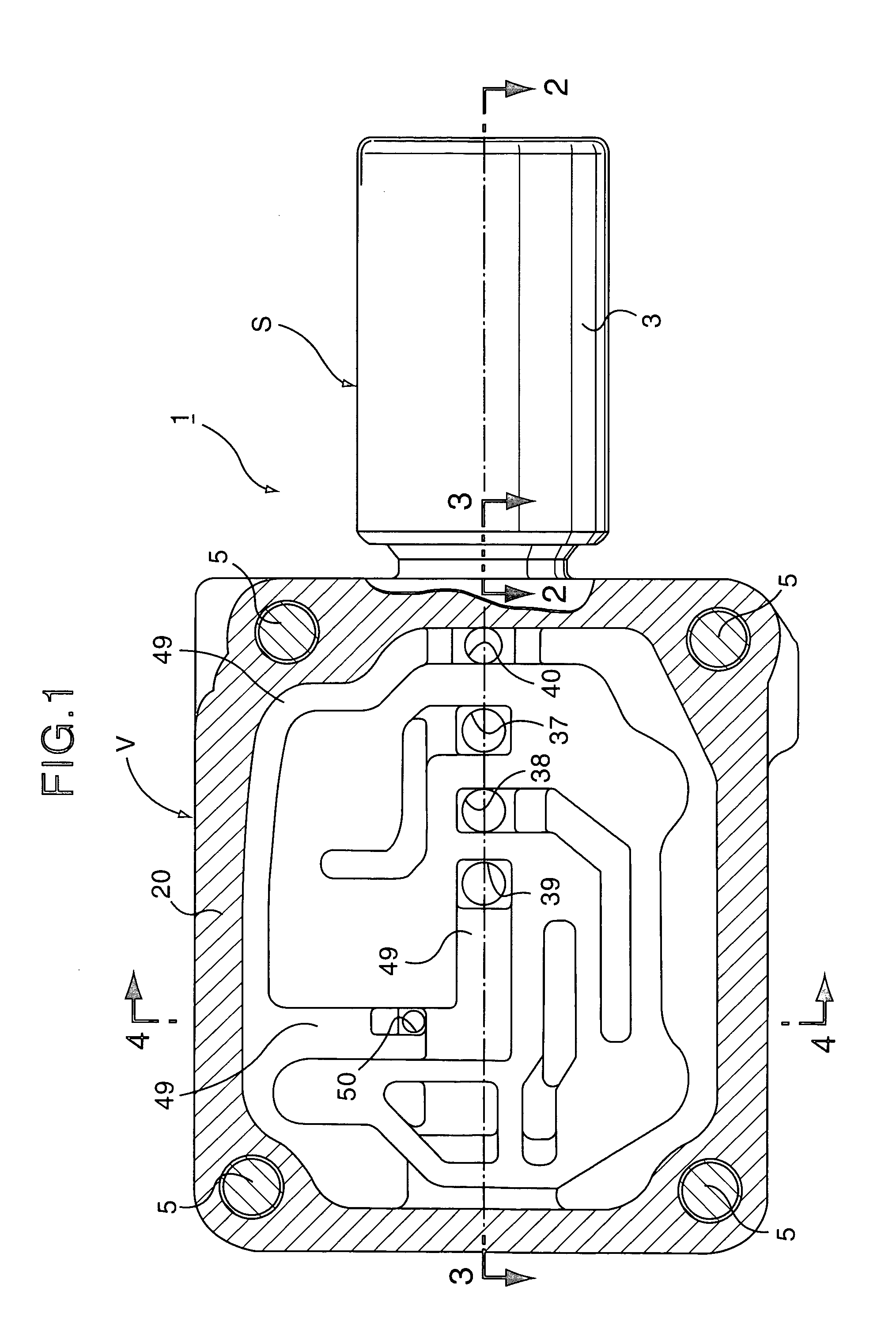
[0036]Referring to FIG. 1, a hydraulic control valve 1 is for controlling clutch hydraulic pressure in, for example, an automatic transmission for an automobile, and is constituted of a linear solenoid unit S and a valve unit V. A valve body 20 of the valve unit V is joined with a bolt 5 to a top surface 2a of a transmission case 2 (see FIG. 4) of an automobile.

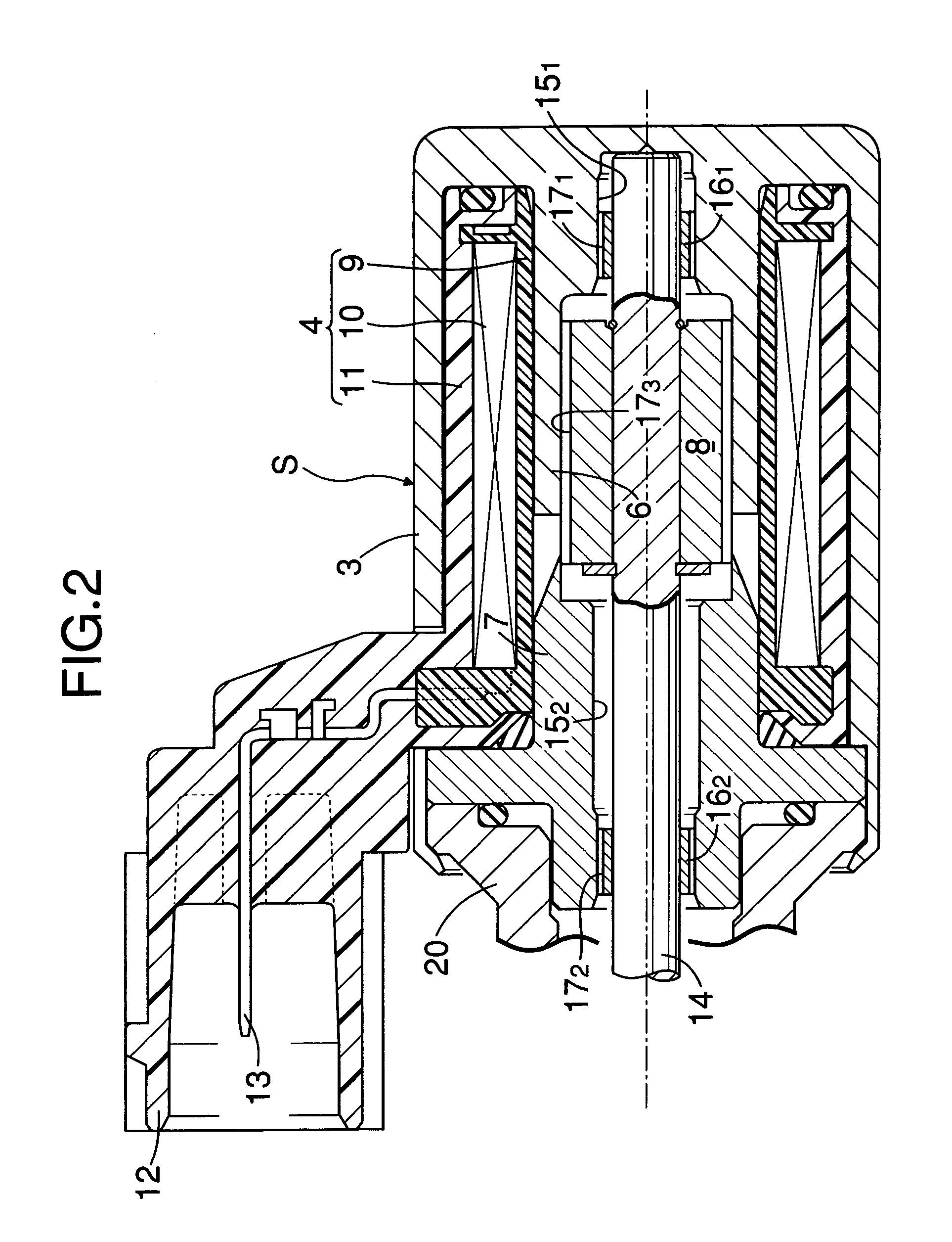
[0037]As shown in FIG. 2, the linear solenoid unit S includes: a housing 3 made of a magnetic material in a bottomed cylindrical shape with one end opened; a coil assembly 4 housed in this housing 3; a cylindrical yoke 6 integrally connected to a closed end wall of the housing 3 and placed inside the coil assembly 4; a fixed core 7 connected to the open end of the housing 3, and placed inside the coil assembly 4 to oppose to the yoke 6 with a predetermined space from the yoke 6; and a movable core 8 slidably fitted in the yoke 6 and the fixed core 7. The ...

second embodiment

[0062]Next, the present invention shown in FIG. 5 will be explained.

[0063]In the second embodiment, the oil reservoir chamber 49 is constructed to be compact, and a drain pipe 53, which rises at the drain oil hole 52 and extends to a position above the orifice 50, is mounted in the transmission case 2. The other parts of construction are the same as in the previous embodiment, and therefore the parts corresponding to the previous embodiment are given the identical reference numerals and characters in FIG. 5, and the explanation of them will be omitted.

[0064]According to the second embodiment, the oil stored in the oil reservoir chamber 49 does not overflow unless the oil level reaches the upper end of the drain pipe 53, which is located at the position above the orifice 50. Therefore, the orifice 50 can be submerged in the oil of the oil reservoir chamber 49, though the oil reservoir chamber 49 is constructed to be compact.

third embodiment

[0065]Next, the present invention shown in FIG. 6 will be explained.

[0066]In the third embodiment, the outer peripheral surface of the third land portion 253 is constructed by connecting a reduced diameter cylindrical surface 253c, which is in place of the taper surface 253b of the first embodiment, to the cylindrical slide surface 253a via an annular step portion. Since the other parts of construction are the same as in the first embodiment, the parts corresponding to the first embodiment are given the identical reference numerals and characters in FIG. 6, and the explanation of them will be omitted.

[0067]Also in the third embodiment, even when the third land portion 253 receives side thrust for some reason and is moved to one side of the fourth annular land portion 314, one side portion of the cylindrical slide surface 253a abuts to the inner peripheral surface of the fourth annular land portion 314, but the reduced diameter cylindrical surface 253c does not contact the fourth ann...


PUM


Abstract

A normally open hydraulic control valve includes: a linear solenoid unit; a spool driven by an output force of the linear solenoid unit to move forward; a valve body in which the spool is fitted; and a return spring for biasing the spool in a retreating direction. The valve body includes: a reaction force oil chamber for introducing hydraulic pressure, which presses the spool in a direction against a biasing force of the return spring, from the output port; and a damper oil chamber which suppresses vibration of the spool. The damper oil chamber is adjacent to the reaction force oil chamber with the third land portion of the spool therebetween. A slide gap which leaks and supplies oil from the reaction force oil chamber to the damper oil chamber is provided between the third land portion and the valve body. Thus, it is possible to quickly supply the oil to the damper oil chamber at the early stage of the operation without restriction on the arrangement, and to prevent delay in operation of the damper oil chamber.

Description

BACKGROUND OF THE INVENTION[0001]1. Field of the Invention[0002]The present invention relates to improvement of a normally open hydraulic control valve comprising: a linear solenoid unit; a spool driven by an output force of the linear solenoid unit to move forward; a valve body in which the spool is slidably fitted; and a return spring for biasing the spool in a retreating direction, the valve body including: a supply port leading to a hydraulic pressure source; an output port leading to a hydraulic pressure operating unit; a drain port opened into an oil tank; a reaction force oil chamber for introducing hydraulic pressure, which presses the spool in a direction against a biasing force of the return spring, from the output port; and a damper oil chamber to which one end surface of the spool is faced and which suppresses vibration of the spool, the spool being constructed to provide blockage between the output port and the drain port at a retreat limit of the spool to provide commu...

Claims


Application Information

Patent Timeline
Patent Type & Authority Patents(United States)
IPC IPC(8): F16K31/06F15B13/04
CPCF15B13/0402F16K31/0613F15B13/0407Y10T137/86622Y10T137/8671
Inventor INO, TOHRURYUEN, SHIGETOWATANABE, HIDETOSHINODA, SATOSHI
Owner KEIHIN CORP
Why Eureka
Try Eureka