
Snowmobile drivetrain

Inactive Publication Date: 2006-09-12
POLARIS IND INC (US)
View PDF45 Cites 1 Cited by
  • Summary
  • Abstract
  • Description
  • Claims
  • Application Information

AI Technical Summary

Benefits of technology

[0015]In one aspect of the present invention, the speed reduction mechanism is disposed below a reference plane defined by a top surface of the drive track. Placing the speed reduction mechanism in a relatively low position may serve to lower the center of gravity of a snowmobile including the speed reduction mechanism. A snowmobile with a lower center of gravity may be more stable and is less likely to overturn.
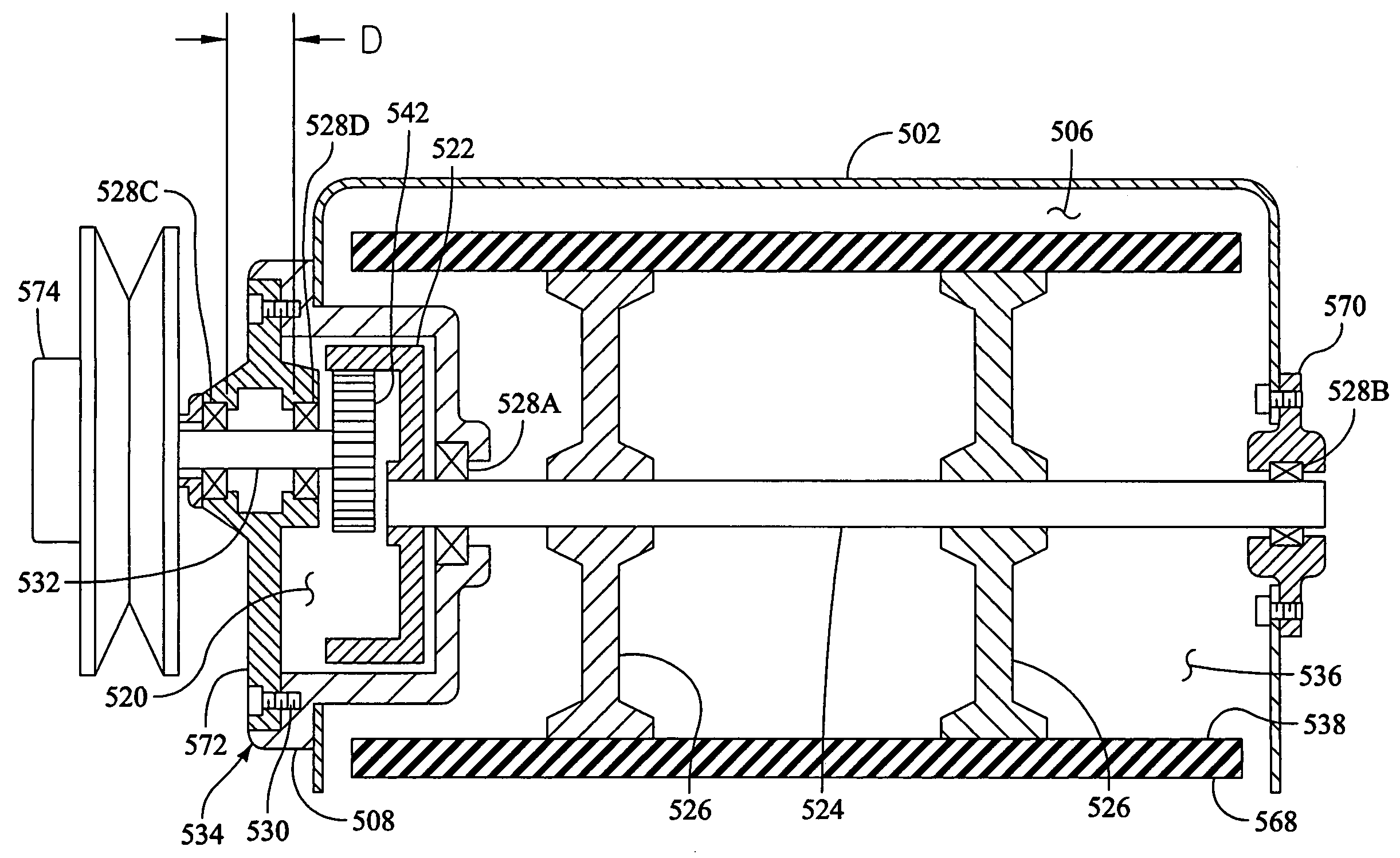
[0016]In an additional aspect of the present invention, a speed reduction mechanism having a compact shape is provided. In certain advantageous implementations, the compact shape of the speed reduction mechanism allows the speed reduction mechanism to be disposed within an interior defined by the inner surface of the drive track. In certain particularly advantageous implementations, the compact shape of the speed reduction mechanism allows the speed reduction mechanism to be disposed within a projection extending from a drive sprocket coupled to the speed reduction mechanism by a drive shaft. Providing a speed reduction mechanism having a compact arrangement, and positioning this speed reduction mechanism in a central location of a snowmobile may serve to provide a snowmobile having a reduced moment of inertia. When a snowmobile has a reduced moment of inertia the rider can more easily make quick changes in the angular orientation and rotational velocity of the snowmobile.
[0017]In yet another aspect of the present invention, a speed reduction mechanism may be provided which has less rotating mass than other types of speed reduction mechanisms. Providing a speed reduction mechanism with a lower rotating mass serves to provide a snowmobile having quicker acceleration. Quick acceleration may be advantageous in high performance applications such as snowmobile racing.
[0018]In still another aspect of the present invention, a method for easily changing the gear ratio of a speed reduction mechanism is provided. This method allows a rider to change the gear ratio to tune the snowmobile for a particular set of riding conditions. A method of changing a gear ratio of a drivetrain in accordance with the present invention may comprise the steps of 1) providing a speed reduction mechanism including a ring gear fixed to a drive shaft, 2) providing an original assembly fixed to the speed reduction mechanism, the original assembly including an original drive gear rotatably supported by an original mounting plate, 3) providing a new assembly including a new drive gear rotatably supported by a new mounting plate, the new drive gear having an effective diameter different than an effective diameter of the original drive gear, 4) removing the original assembly from the speed reduction mechanism, and 5) installing the new assembly onto the speed reduction mechanism.

Problems solved by technology

Modern snowmobiles, can cover ground very rapidly and can cover great distances.
For example, the inertia of an overly heavy snowmobile may limit how rapidly that snowmobile can accelerate and decelerate.

Method used


Image

  • Snowmobile drivetrain
  • Snowmobile drivetrain
  • Snowmobile drivetrain

Examples


Embodiment Construction

[0039]The following detailed description should be read with reference to the drawings, in which like elements in different drawings are numbered identically. The drawings, which are not necessarily to scale, depict selected embodiments and are not intended to limit the scope of the invention. Examples of constructions, materials, dimensions, and manufacturing processes are provided for selected elements. All other elements employ that which is known to those of skill in the field of the invention. Those skilled in the art will recognize that many of the examples provided have suitable alternatives that can be utilized.

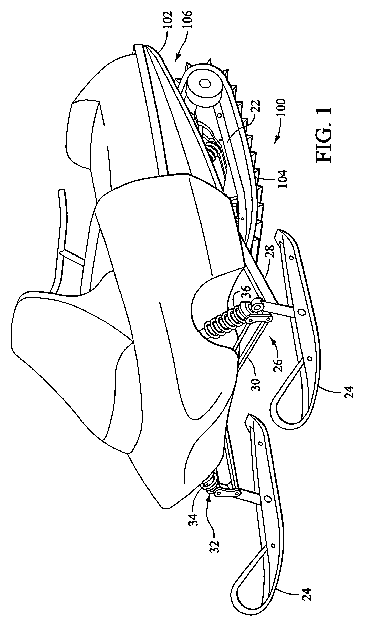
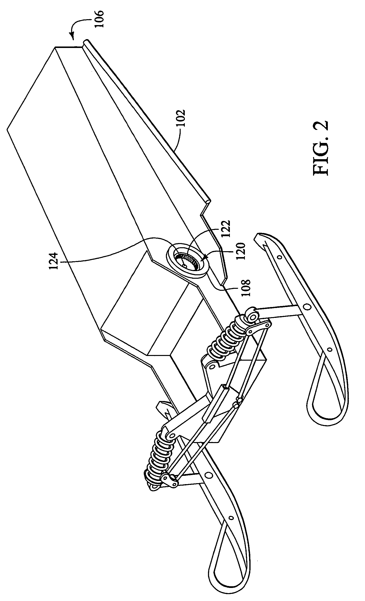
[0040]FIG. 1 is a perspective view of a snowmobile 100 in accordance with an exemplary embodiment of the present invention. Snowmobile 100 has a chassis 102 defining a tunnel 106. In the embodiment of FIG. 1, a drive track 104 can be seen extending from tunnel 106. In the embodiment of FIG. 1, drive track 104 comprises an endless loop that is supported by a rear suspe...


PUM


Abstract

Methods and apparatus for propelling snowmobiles are disclosed. A snowmobile in accordance with an exemplary embodiment of the present invention comprises a chassis defining a tunnel, a drive shaft at least partially disposed in the tunnel, and at least one drive sprocket fixed to the drive shaft. A drive track overlays a portion of the at least one drive sprocket. A bearing is disposed within an interior of the drive track for rotatably supporting the drive shaft. The drive shaft is preferably operatively coupled to an engine by a drivetrain. In an advantageous embodiment, the drivetrain comprising a reduction mechanism that is substantially disposed within the tunnel defined by the chassis. In a particularly advantageous embodiment, the reduction mechanism is disposed within a projection extending from a drive sprocket fixed to the drive shaft.

Description

RELATED APPLICATIONS[0001]This is a Division of application Ser. No. 10 / 137,970 filed May 3, 2002 now U.S. Pat. No. 6,755,271.[0002]This application is related to and claims priority to U.S. Provisional Application No. 60 / 318,151, filed Sep. 7, 2001, and entitled Snowmobile Drivetrain.[0003]This application is also related to and claims priority to U.S. Provisional Application No. 60 / 317,892, filed Sep. 7, 2001, and entitled Snowmobile Providing an Enhanced Riding Experience.[0004]The entire disclosure of the fore mentioned applications is hereby incorporated by reference.FIELD OF THE INVENTION[0005]The present invention relates generally to snowmobiles. More particularly, the present invention relates to methods and apparatus for propelling snowmobiles.BACKGROUND OF THE INVENTION[0006]Since their development in the middle of the 20th century, snowmobiles have gained widespread popularity. Snowmobiles are commonly used for trail riding and utility applications. Perhaps the most comm...

Claims


Application Information

Patent Timeline
IPC IPC(8): B62M27/02
CPCB62M27/02B62M2027/023
Inventor BERG, NORMAN O.
Owner POLARIS IND INC (US)
Learn More