Low pressure fuel injector nozzle

a fuel injector and low pressure technology, applied in the field of fuel injectors, can solve the problems of increasing emissions, reducing combustion efficiency, and difficult direction, and achieve the effects of enhancing atomization, enhancing spray angle, and enhancing atomization

Inactive Publication Date: 2006-09-12
VISTEON GLOBAL TECH INC
View PDF112 Cites 23 Cited by
  • Summary
  • Abstract
  • Description
  • Claims
  • Application Information

AI Technical Summary

Benefits of technology

[0005]One embodiment of the present invention provides a nozzle for a low pressure fuel injector which increases the spray angle, provides control over the direction of the spray, and enhances atomization of the fuel delivered to a cylinder of an engine. The nozzle generally comprises a nozzle body and a metering plate. The nozzle body defines a valve outlet and a longitudinal axis. The metering plate is connected to the nozzle body and is in fluid communication with the valve outlet. The metering plate defines a nozzle cavity receiving fuel from the valve outlet. The metering plate defines a plurality of exit cavities receiving fuel from the nozzle cavity. Each exit cavity is radially spaced from the longitudinal axis and meets the nozzle cavity at a first exit orifice. A rib projects into the exit cavity and separates an upstream portion and a downstream directing portion of the exit cavity. The rib defines a second exit orifice having a diameter less than the first exit orifice.
[0007]According to still further details, each exit cavity defines an exit axis. Each exit axis is tilted in the radial direction relative to the longitudinal axis. In this manner, the exit cavities increase the spray angle of the nozzle. The exit axis is also preferably tilted in a tangential direction relative to the longitudinal axis. In this manner, the exit cavities produce a swirl component to the fuel exiting the nozzle that enhances atomization of the fuel. A variation of the exit cavity may be employed where the upstream portion defines an upstream axis and the downstream directing portion defines a downstream axis. In this variation, the downstream axis is not aligned with the upstream axis. Accordingly, it will be seen that the unique structure of the nozzle permits an increase in the spray angle as well as better control over the direction of the spray. At the same time, the first and second exit cavities, as well as the cavitating flow region, enhance the atomization of the fuel delivered to the cylinder of the engine.
[0009]According to more detailed aspects, the exit cavity is preferably cylindrical and has a constant diameter. The exit orifice and the exit cavity generate a cavitating flow region which enhances the atomization of the fuel. The rib preferably tapers to a sharp edge to further assist the atomization of the fuel. Each exit cavity defines an exit axis, and each exit axis may be tilted in either or both of the radial direction and the tangential direction relative to the longitudinal axis. In this manner, the spray angle of the nozzle may be increased, and a swirl component may be introduced into the fuel exiting the nozzle to enhance atomization.

Problems solved by technology

However, a higher fuel delivery pressure causes greater dissipation of the fuel within the cylinder, and propagates the fuel further outward away from the injector nozzle.
This propagation makes it more likely that the fuel spray will condense on the walls of the cylinder and the top surface of the piston, which decreases the efficiency of the combustion and increases emissions.
However, the relatively low pressure of the fuel and the sharp edges result in the spray being difficult to direct and reduces the range of the spray.

Method used


Image

  • Low pressure fuel injector nozzle
  • Low pressure fuel injector nozzle
  • Low pressure fuel injector nozzle

Examples


Embodiment Construction

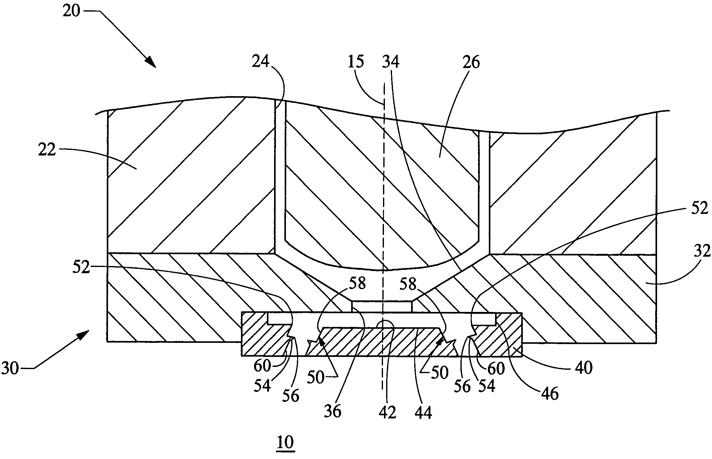
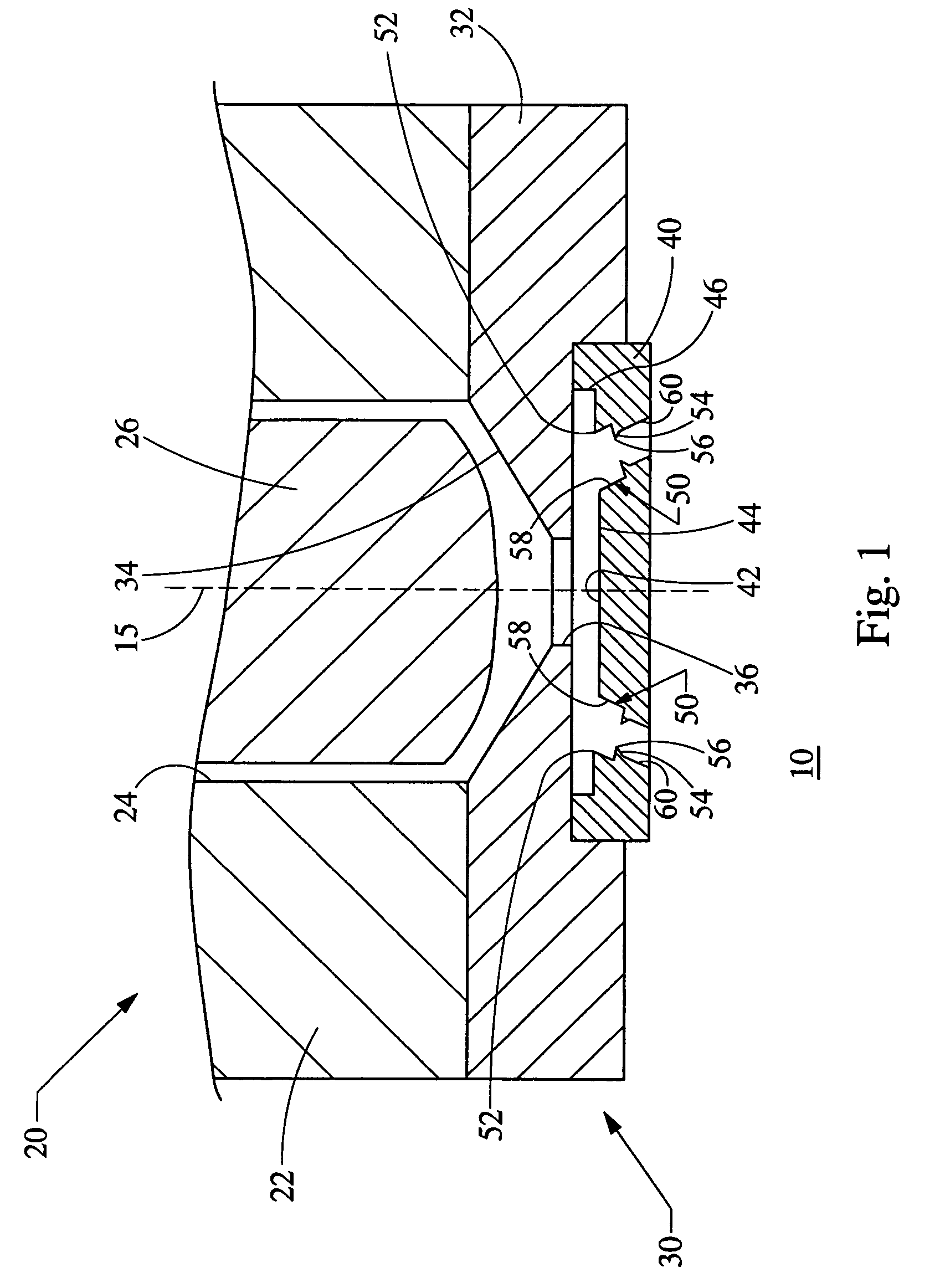
[0016]Turning now to the figures, FIG. 1 depicts a cross-sectional of a nozzle 20 constructed in accordance with the teachings of the present invention. The nozzle 20 is formed at a lower end of a low pressure fuel injector which is used to deliver fuel to a cylinder 10 of an engine, such as an internal combustion engine of an automobile. An injector body 22 defines an internal passageway 24 having a needle 26 positioned therein. The injector body 22 defines a longitudinal axis 15, and the internal passageway 24 extends generally parallel to the longitudinal axis 15. A lower end of the injector body 22 defines a nozzle body 32. It will be recognized by those skilled in the art that the injector body 22 and nozzle body 32 may be integrally formed, or alternatively the nozzle body 32 may be separately formed and attached to the distal end of the injector body 22 by welding or other well known techniques.

[0017]In either case, the nozzle body 32 defines a valve seat 34 leading to a valv...


PUM


Abstract

A nozzle for a low pressure fuel injector that improves the control and size of the spray angle, as well as enhances the atomization of the fuel delivered to a cylinder of an engine.

Description

FIELD OF THE INVENTION[0001]The present invention relates generally to fuel injectors for automotive engines, and more particularly relates to fuel injector nozzles capable of atomizing fuel at relatively low pressures.BACKGROUND OF THE INVENTION[0002]Stringent emission standards for internal combustion engines suggest the use of advanced fuel metering techniques that provide extremely small fuel droplets. The fine atomization of the fuel not only improves emission quality of the exhaust, but also improves the cold weather start capabilities, fuel consumption and performance. Typically, optimization of the droplet sizes dependent upon the pressure of the fuel, and requires high pressure delivery at roughly 7 to 10 MPa. However, a higher fuel delivery pressure causes greater dissipation of the fuel within the cylinder, and propagates the fuel further outward away from the injector nozzle. This propagation makes it more likely that the fuel spray will condense on the walls of the cyli...

Claims


Application Information

Patent Timeline
Patent Type & Authority Patents(United States)
IPC IPC(8): F02M59/00B05B1/30F02M47/02F02M61/00
CPCF02M61/1806F02M61/1853F02M61/1833
Inventor GOENKA, LAKHI N.MARA, JEFFREY PAULPORTER, DAVID LEEHUNG, DAVID LING-SHUNSTEFANSKI, JOHN
Owner VISTEON GLOBAL TECH INC
Why Eureka
Try Eureka