Fence post protecting apparatus

a technology for protecting apparatus and fence posts, which is applied in the direction of plant protective coverings, buildings, and buildings. it can solve the problems of severing the line, damaging the monofilament line of the fence post, and sharp corners of the square fence post that are particularly damaging to the monofilament line, etc., and achieves the effect of sufficient thickness

Inactive Publication Date: 2006-09-12
RICCI JEFFREY W
View PDF16 Cites 44 Cited by
  • Summary
  • Abstract
  • Description
  • Claims
  • Application Information

AI Technical Summary

Benefits of technology

[0014]The present invention also includes a base portion integral with the plurality of sidewalls and extending about a perimeter of the collar section. The base portion defines a flange portion that has a top surface sloping downwardly and away from the fence post. Such a base portion is preferably contiguous with the plurality of sidewalls and is engageable with a ground surface for effectively assisting to maintain the collar section at a substantially stable position during operating conditions. Advantageously, fluid is conveniently directed outwardly and away from the plurality of sidewalls so that the apparatus does not become damaged from environmental conditions.

Problems solved by technology

Many forms of fencing, particularly privacy fencing which uses square wooden fence posts, have corners between the fence posts and the fencing where vegetation can grow and attempts to trim around these posts often results in damage to the posts and / or to the trimmer's monofilament line.
Sharp corners on square fence posts are particularly damaging to monofilament line and may even sever the line.
This drastically reduces the useful life of a standard line supply for such a trimmer.
In addition to the waste of monofilament, this results in a waste of time while the monofilament supply is replaced and the trimmer is rethreaded.
Furthermore, exposure to rain, snow, and extreme temperatures may cause the wooden posts to swell, shrink, crack, or warp.
The physical deformities caused be environmental factors can result in the need for the fence to be replaced.

Method used


Image

  • Fence post protecting apparatus
  • Fence post protecting apparatus
  • Fence post protecting apparatus

Examples


Embodiment Construction

[0021]The present invention will now be described more fully hereinafter with reference to the accompanying drawings, in which a preferred embodiment of the invention is shown. This invention may, however, be embodied in many different forms and should not be construed as limited to the embodiment set forth herein. Rather, this embodiment is provided so that this application will be thorough and complete, and will fully convey the true scope of the invention to those skilled in the art. Like numbers refer to like elements throughout the figures.

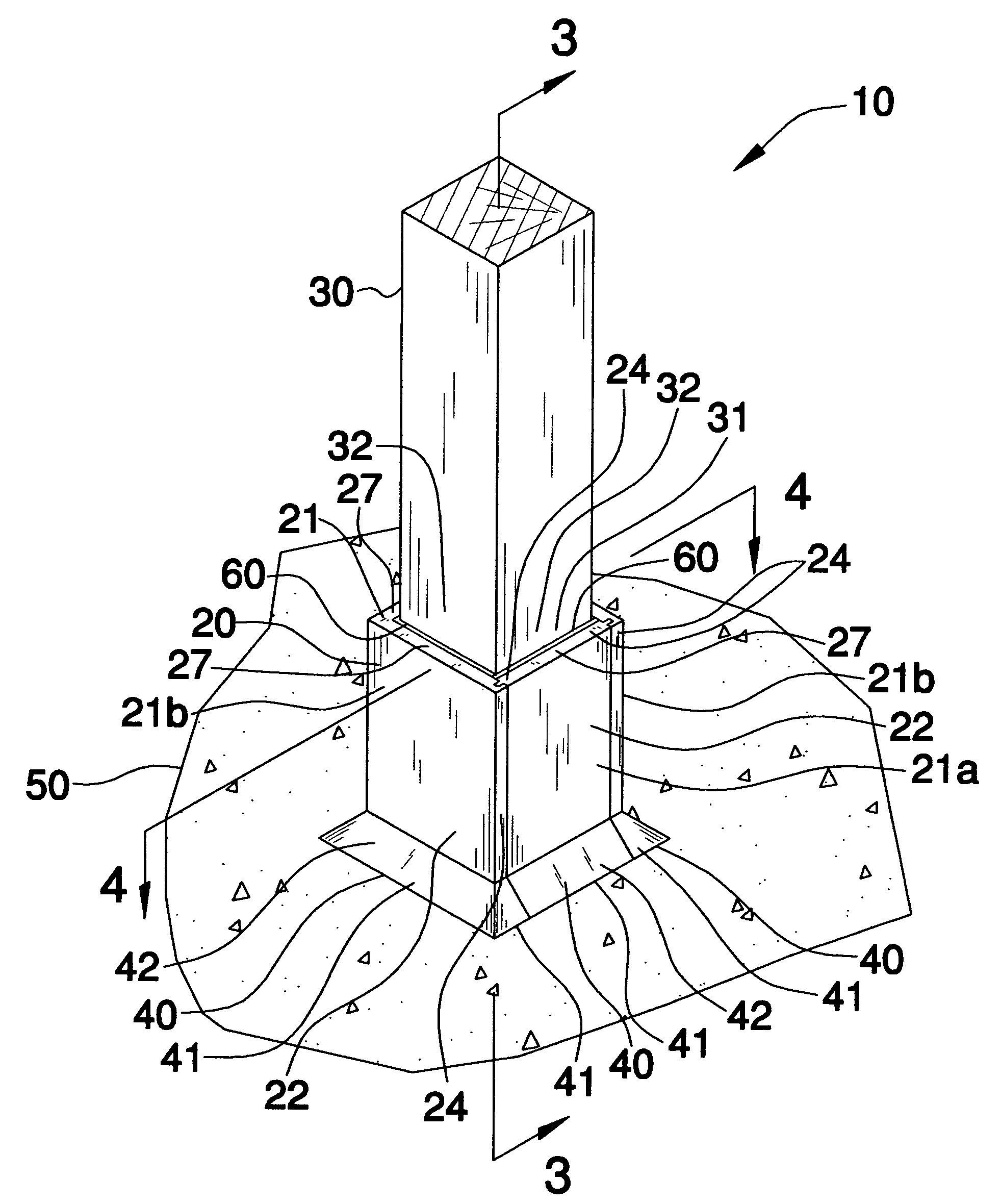
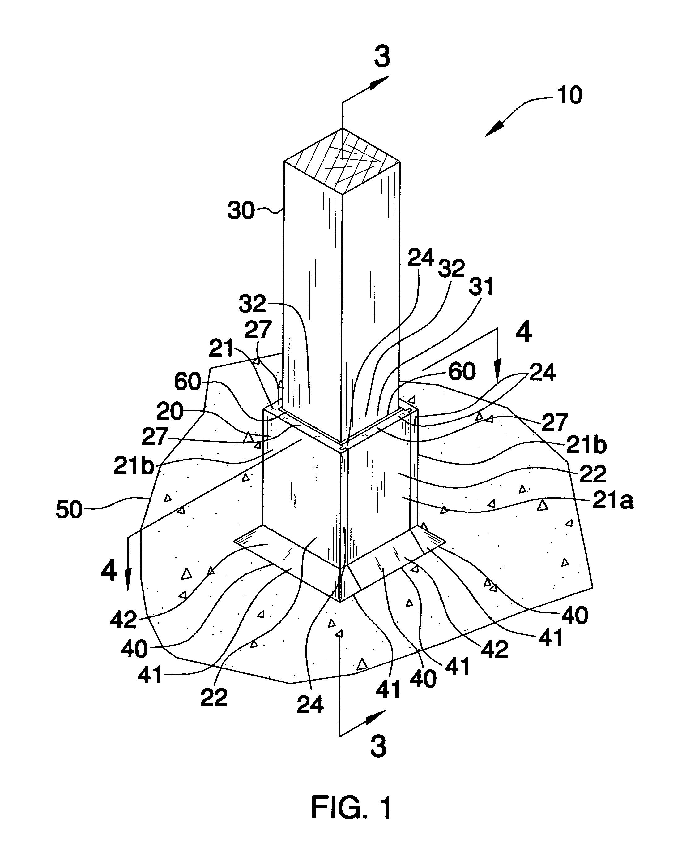
[0022]The apparatus of this invention is referred to generally in FIGS. 1–4 by the reference numeral 10 and is intended to provide a fence post protector. It should be understood that the apparatus 10 may be used to protect many different types of structures and should not be limited to only conventional fence posts having a square cross-section.

[0023]Referring initially to FIG. 1, the apparatus 10 includes a collar section 20 formed from non...


PUM


Abstract

An apparatus for shielding a fence post from foreign elements includes a collar section with integral sidewalls, one detachable sidewall, a base extending about a perimeter of the collar section, and a mechanism for preventing fluid from traveling distally and medially of an outer wall of the fence post and an inner perimeter of the collar. The detachable sidewall is provided with oppositely spaced tongue portion and the collar section has a pair of grooves formed therein. The tongue and groove portions are slidably engageable with each other so that the apparatus can be assembled and disassembled by moving the detachable sidewall along a substantially vertical plane. The fluid blocking mechanism preferably includes a rubber seal contiguously positioned medially of the fence post and collar section.

Description

CROSS REFERENCE TO RELATED APPLICATIONS[0001]Not Applicable.STATEMENT REGARDING FEDERALLY SPONSORED RESEARCH OR DEVELOPMENT[0002]Not Applicable.REFERENCE TO A MICROFICHE APPENDIX[0003]Not Applicable.BACKGROUND OF THE INVENTION[0004]1. Technical Field[0005]This invention relates to outdoor post protectors and, more particularly, to a detachable protective cover for shielding a fence post from foreign elements.[0006]2. Prior Art[0007]Much of the residential and commercial property in this country uses fencing to provide privacy and / or define property lines. While the fencing itself is relatively maintenance-free, vegetation abutting such fencing, particularly lawns, requires regular and frequent maintenance in the form of trimming.[0008]Many forms of fencing, particularly privacy fencing which uses square wooden fence posts, have corners between the fence posts and the fencing where vegetation can grow and attempts to trim around these posts often results in damage to the posts and / or...

Claims


Application Information

Patent Timeline
Patent Type & Authority Patents(United States)
IPC IPC(8): E04H17/14E04H17/00
CPCE04H12/2292
Inventor RICCI, JEFFREY W.
Owner RICCI JEFFREY W
Why Eureka
Try Eureka