Inserting apparatus and method with controlled, master cycle speed-dependent actuator operations

a master cycle speed and actuator technology, applied in the direction of digital computer details, instruments, packaged goods types, etc., can solve the problem that machines are not capable of operating at different cycle speeds, and achieve the effect of maintaining synchronization and constant time lag

Inactive Publication Date: 2005-11-03
BELL & HOWELL CO
View PDF26 Cites 103 Cited by
  • Summary
  • Abstract
  • Description
  • Claims
  • Application Information

AI Technical Summary

Benefits of technology

[0013] The present invention provides a method for controlling a machine that operates over a master cycle at variable cycle speeds, and that includes one or more assemblies which perform rotational movements in synchrony and in combination with one or more other actuated peripheral devices. The peripheral devices are activated by actuators such as solenoids known to exhibit generally constant time lags. Conventionally, such machines are not capable of operating at different cycle speeds, since such a change has in the past thrown the rotational assemblies out of synchronization with the peripheral devices. The method according to the present invention, however, has the advantageous feature of being able to make on-the-fly adjustments to solenoid timing in response to changing cycle speed, and thus efficiently maintain synchronization. This method is implemented by a motion controller or other suitable device capable of electronic processing of an instruction set for performing position-based velocity compensation. The method has been successfully demonstrated in the environment of a continuous motion inserting apparatus, such as the type employed in mail processing jobs, although it will be understood that the present invention will have application outside the immediate scope of the continuous motion inserting apparatus. The present invention can be implemented in mail inserting machines other than the continuous-motion type, as well as any machine requiring synchronization among rotational and actuated components.
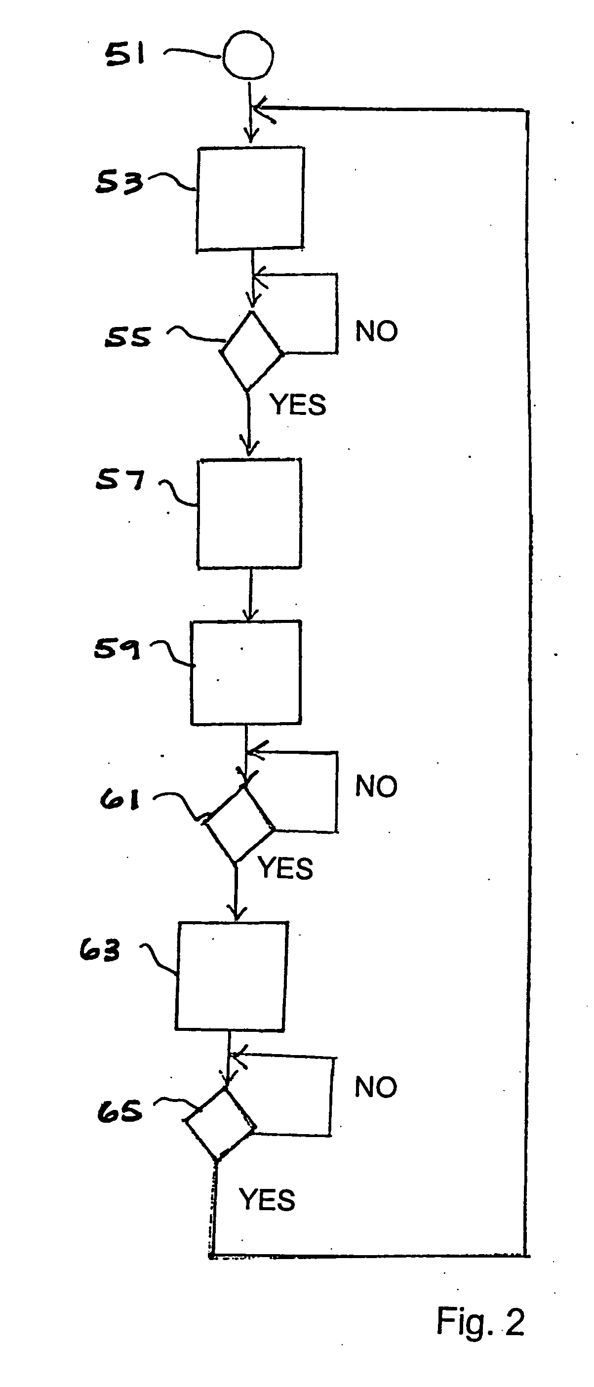
[0019] According to a still further embodiment of the present invention, a method is provided for continuously inserting inserts into corresponding envelopes in a controlled manner, and over a range of master cycle speeds at which an inserting apparatus operates. The method encompasses monitoring a master cycle speed at which an inserting apparatus operates over a plurality of master cycles, and determining when a new master cycle has begun. Once during every master cycle of operation of the inserting apparatus, a first calculation is performed. The first calculation determines a first cyclical position of the new master cycle at which an actuated device should begin to be activated. The calculation is based on the master cycle speed measured for the new master cycle, a predetermined time duration required for the actuated device to become fully active, and a predetermined cyclical position of the new master cycle at which the actuated device should be fully active. The actuated device is caused to begin to be activated when the new master cycle reaches or exceeds the calculated first cyclical position. Activation of the actuated device assists in an inserting process performed by the inserting apparatus, such as by opening an envelope prior to insertion, registering an envelope, or transporting the stuffed envelope away at the correct point in time during the machine cycle.
[0021] It is therefore an object of the present invention to provide an improved continuous motion inserting machine and an improved inserting method, wherein tight control and synchronization of the various moving components can be maintained over a wide range of machine speeds.
[0022] It is another object of the present invention to provide an inserting machine and related method that include a motion controller or other electronic processing device, which motion controller is capable of calculating in real time the correct cyclic positioning of certain actuated components during operation of the inserting machine, so that a change in machine speed will not require a reconfiguration of one of more machine components.

Problems solved by technology

Conventionally, such machines are not capable of operating at different cycle speeds, since such a change has in the past thrown the rotational assemblies out of synchronization with the peripheral devices.

Method used


Image

  • Inserting apparatus and method with controlled, master cycle speed-dependent actuator operations
  • Inserting apparatus and method with controlled, master cycle speed-dependent actuator operations
  • Inserting apparatus and method with controlled, master cycle speed-dependent actuator operations

Examples


Embodiment Construction

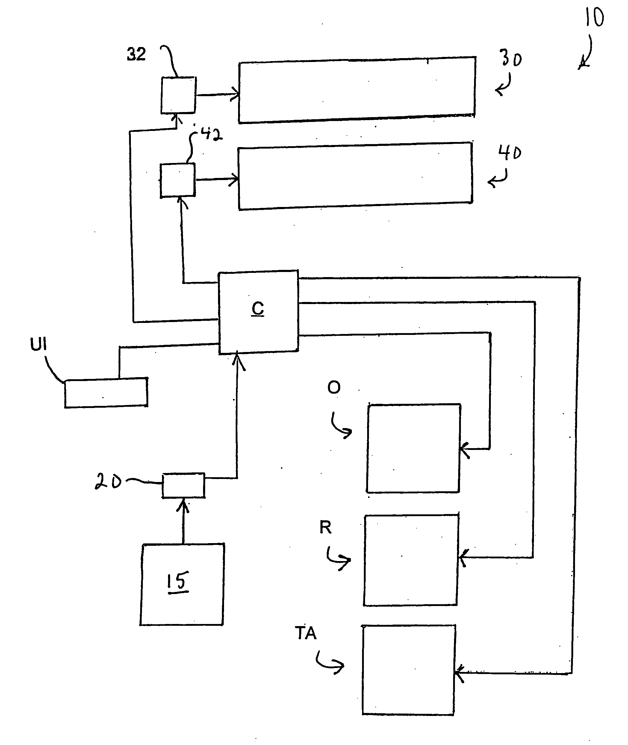
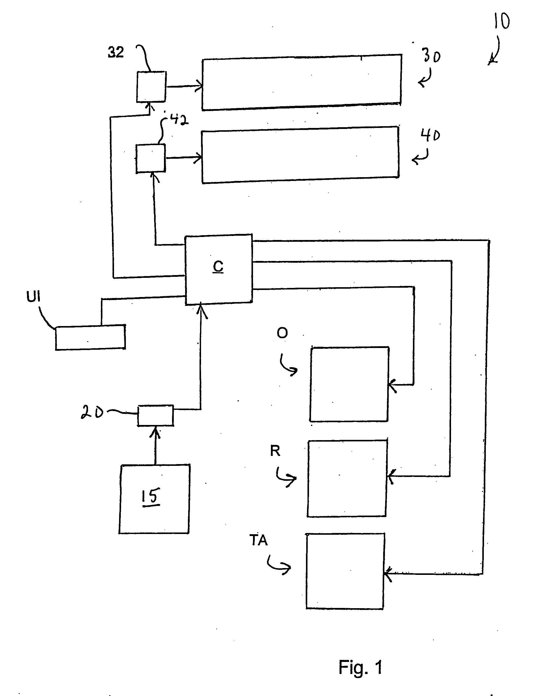
[0035] Referring now to FIG. 1, an inserting apparatus or system, generally designated 10, is schematically illustrated. Inserting apparatus includes a master drive assembly 15 that typically drives a primary function such as the transport of inserts downstream to one or more assemblies associated with insertion apparatus 10. Master drive assembly 15 includes a rotating component (not specifically shown), such as a motor-driven drive shaft, which might be mechanically linked to other rotating components as understood by persons skilled in the art. An encoder 20 or similar device interfaces with the rotating component of master drive assembly 15. Encoder 20 measures the rate at which master drive assembly 15 is physically rotating (i.e., the master cycle speed) in encoder pulses per second, and converts this measurement into an electrical output signal. The encoder signal is read and interpreted by a motion controller C, which includes an I / O interface, signal conditioning and amplif...


PUM

PropertyMeasurementUnit
timeaaaaaaaaaa
dwell timeaaaaaaaaaa

Abstract

In an inserting apparatus and method such as the continuous motion type, a motion controller electrically communicates with an encoder, a first motor driving an insert conveyor assembly, a second motor driving an envelope conveyor assembly, and an actuator operatively interfaced with a peripheral device. The motion controller controls insert conveyor assembly speed, envelope conveyor assembly speed, and the rotational position at which the actuator should be activated, based on the encoder signal. Once during every master cycle, the motion controller calculates the actuator activation position, and causes the first actuator to be activated at the calculated first actuator activation position.

Description

TECHNICAL FIELD [0001] The present invention is generally directed to an inserting apparatus and method, such as the type of apparatus and method useful in performing mail inserting operations in which an insert is inserted into an envelope for subsequent processing. More particularly, the present invention is directed to an inserting apparatus and method capable of adaptively controlling one or more actuated components in response to a change in the cycle speed of the apparatus. BACKGROUND ART [0002] Mail insertion machines implementing continuous motion, or at least substantially continuous motion, have been developed in the past. A basic function of such machines is to establish a flow of inserts, such as documents or other sheet-type products, establish a flow of envelopes, and combine both flows into a single, common feed path. Once a given insert and a given envelope enter the common feed path, the insert must be inserted into the opened envelope at a common insertion point, a...

Claims


Application Information

Patent Timeline
Patent Type & Authority Applications(United States)
IPC IPC(8): B43M3/04B65B43/30B65B1/04C01FH03F1/26
CPCB43M3/045B43M3/04
Inventor RIVENBARK, JAMES R.HARSHMAN, KEITHSHINN, FRANK J.HENRY, BRADFORD D.MCCAY, STEVEN W.MCCAY, KATHLEEN E.
Owner BELL & HOWELL CO
Why Eureka
Try Eureka