

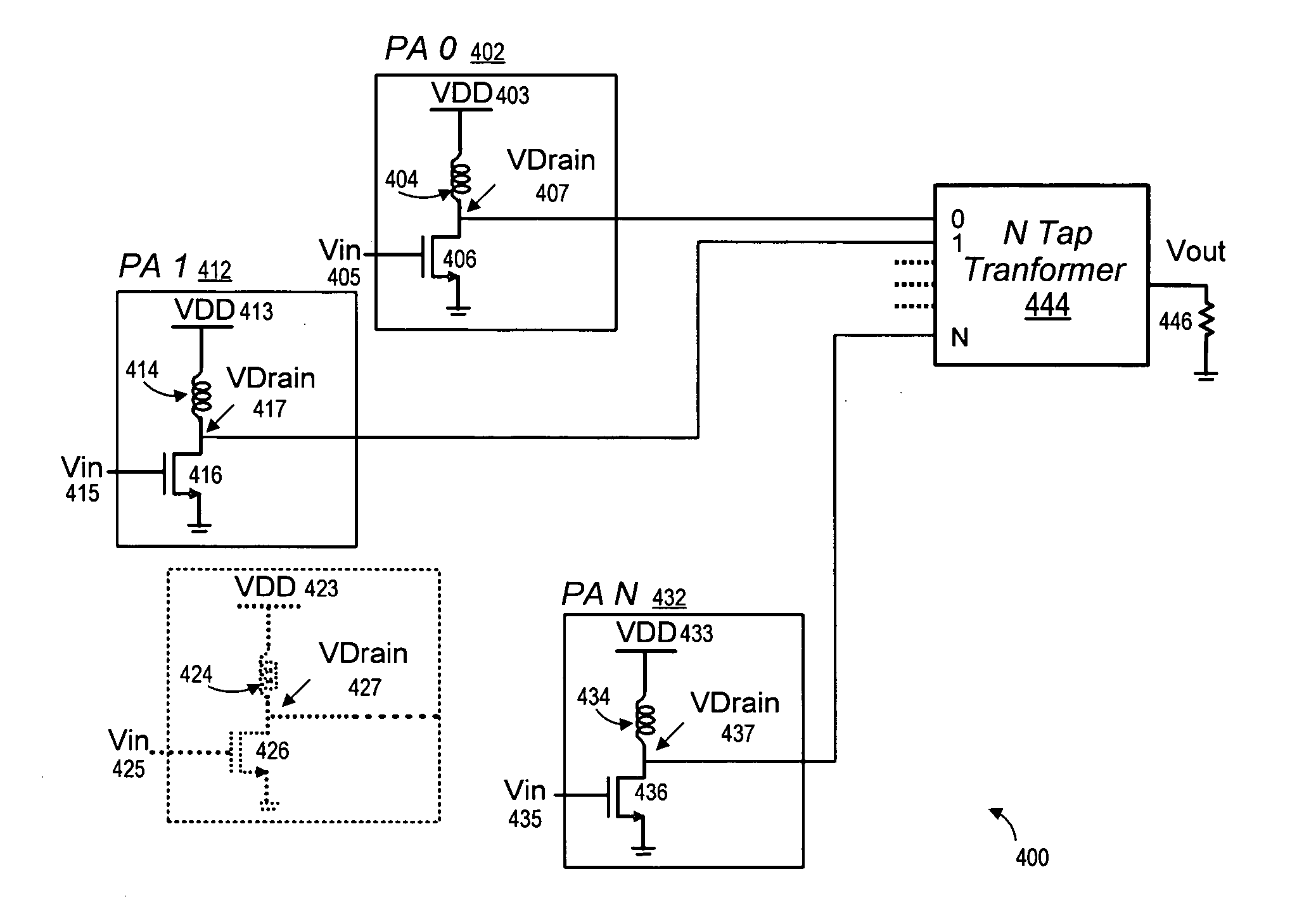
Multilevel power amplifier architecture using multi-tap transformer
a multi-tap transformer and power amplifier technology, applied in amplifiers, amplifiers with semiconductor devices/discharge tubes, amplifiers, etc., can solve the problems of circuit systems posing design challenges, communication system performance requirements and resulting costs, and achieving the effect of power efficiency and maintaining efficiency
- Summary
- Abstract
- Description
- Claims
- Application Information
AI Technical Summary
Benefits of technology
Problems solved by technology
Method used
Image

Examples
Embodiment Construction
[0031] A method and apparatus for an improved power amplifier architecture is described. While various details are set forth in the following description, it will be appreciated that the present invention may be practiced without these specific details. For example, selected aspects are shown in block diagram form, rather than in detail, in order to avoid obscuring the present invention. Some portions of the detailed descriptions provided herein are presented in terms of schematic descriptions and cross-sectional depictions which are used by those skilled in the field of communication systems to describe and convey the substance of their work to others skilled in the art.
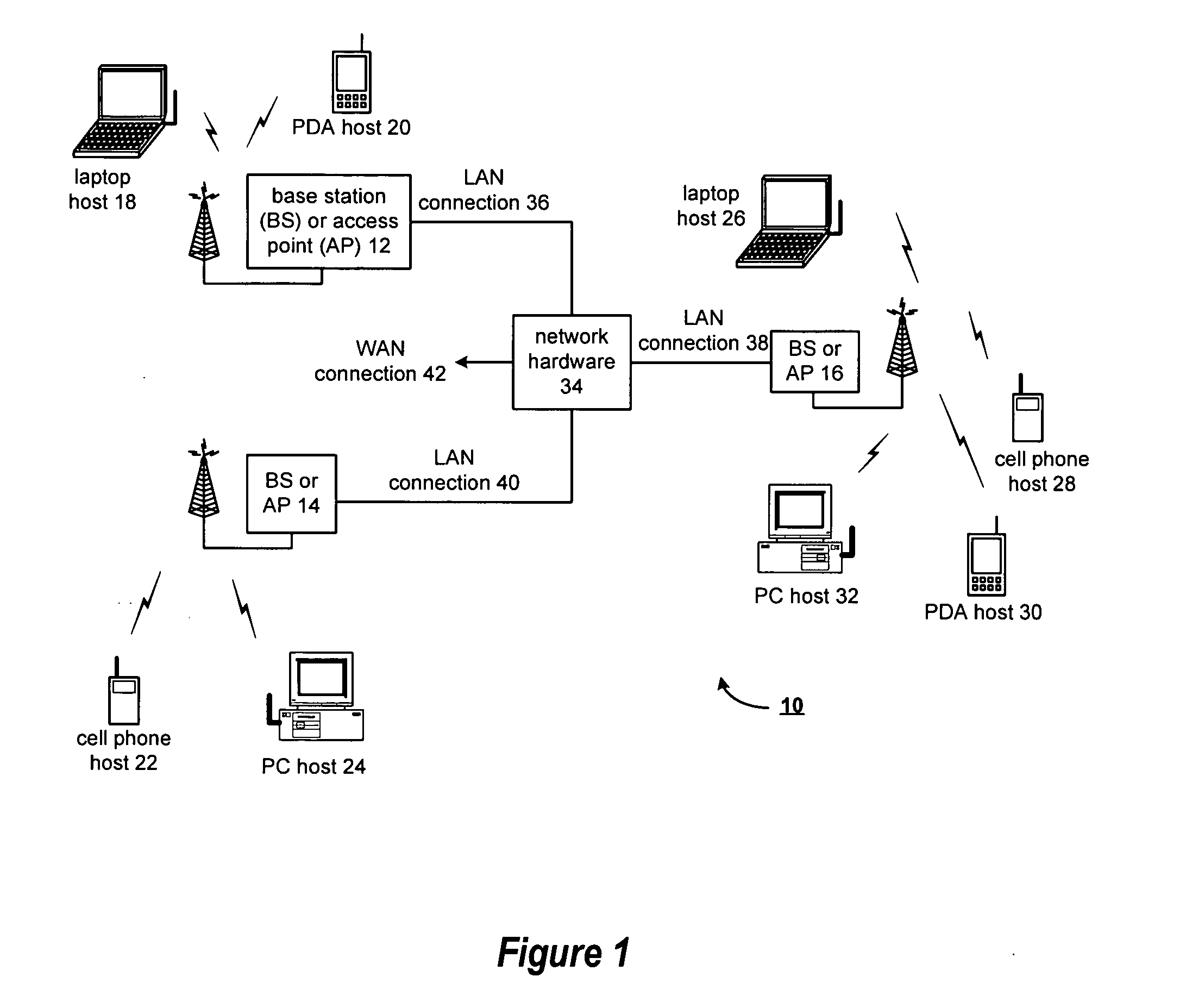
[0032]FIG. 1 illustrates a wireless communication system 10 in which embodiments of the present invention may operate. As illustrated, the wireless communication system 10 includes a plurality of base stations and / or access points 12, 14, 16, a plurality of wireless communication devices 18-32 and a network hardwar...
PUM
 Abstract
Description
Claims
Application Information