
Inserting apparatus and method with controlled, master cycle speed-dependent actuator operations

a master cycle speed and actuator technology, applied in the direction of digital computer details, instruments, packaged goods types, etc., can solve the problem that machines are not capable of operating at different cycle speeds, and achieve the effect of maintaining synchronization and constant time lag

Inactive Publication Date: 2008-07-08
BELL & HOWELL CO
View PDF27 Cites 6 Cited by
  • Summary
  • Abstract
  • Description
  • Claims
  • Application Information

AI Technical Summary

Benefits of technology

This approach maintains precise synchronization and consistent performance across a wide range of machine speeds, reducing the need for manual adjustments and improving the accuracy of the insertion process.

Problems solved by technology

Conventionally, such machines are not capable of operating at different cycle speeds, since such a change has in the past thrown the rotational assemblies out of synchronization with the peripheral devices.

Method used


Image

  • Inserting apparatus and method with controlled, master cycle speed-dependent actuator operations
  • Inserting apparatus and method with controlled, master cycle speed-dependent actuator operations
  • Inserting apparatus and method with controlled, master cycle speed-dependent actuator operations

Examples


Embodiment Construction

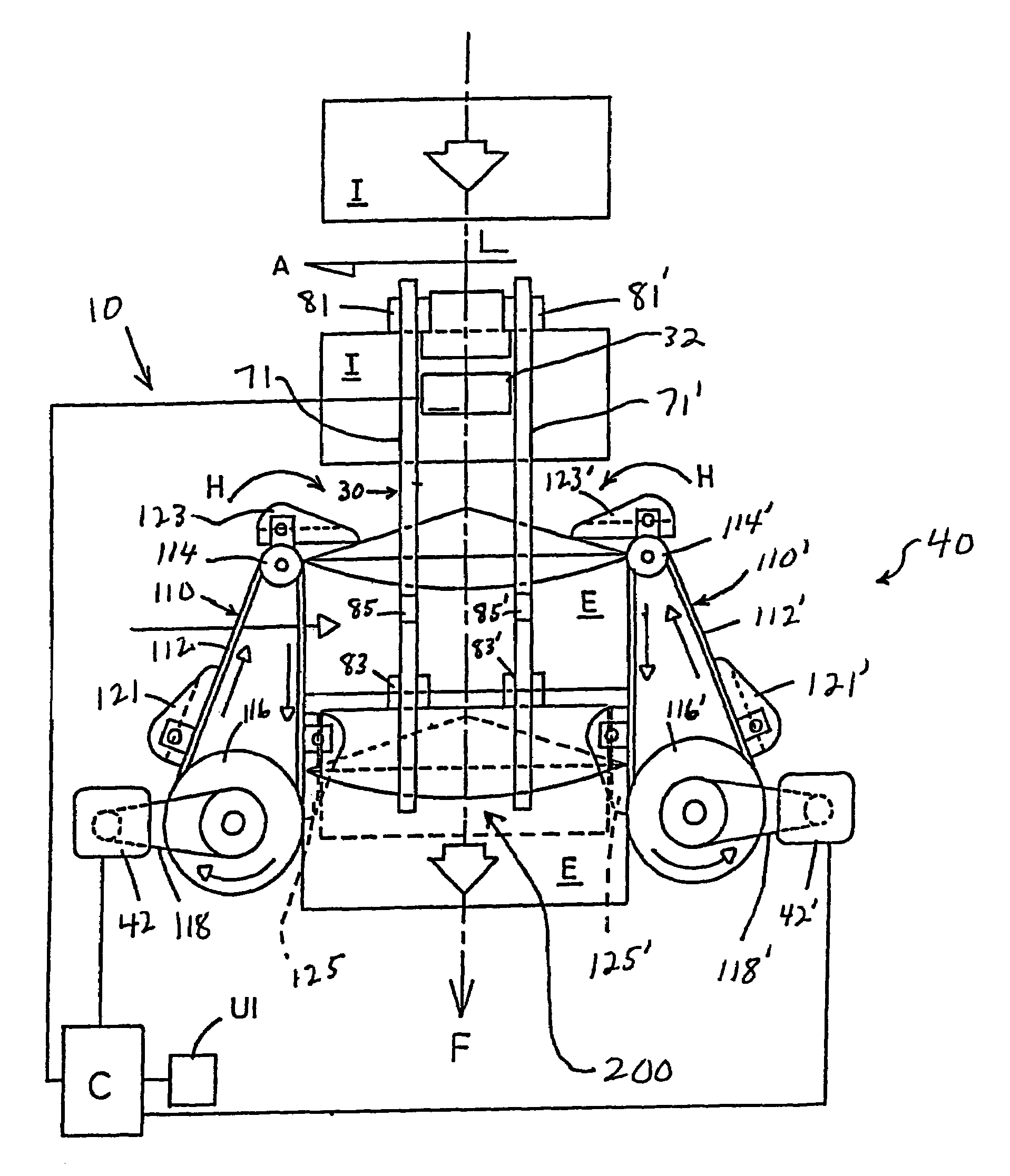
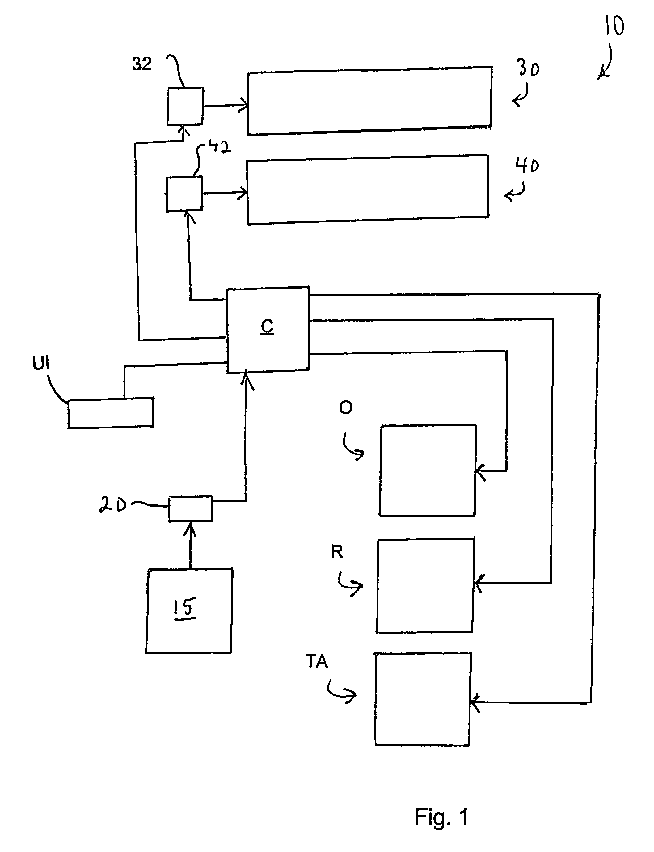
[0036]Referring now to FIG. 1, an inserting apparatus or system generally designated 10, is schematically illustrated. Inserting apparatus 10 includes a master drive assembly 15 that typically drives a primary function such as the transport of inserts downstream to one or more assemblies associated with insertion apparatus 10. Master drive assembly 15 includes a rotating component (not specifically shown), such as a motor driven drive shaft, which might be mechanically linked to other rotating components as understood by persons skilled in the art. An encoder 20 or similar device interfaces with the rotating component of master drive assembly 15. Encoder 20 the rate at which master drive assembly 15 is physically rotating (i.e, the master cycle speed) in encoder pulses per second, and converts this measurement into an electrical output signal. The encoder signal is read and interpreted by a motion controller C, which includes an I / O interface, signal conditioning and amplification e...


PUM

PropertyMeasurementUnit
timeaaaaaaaaaa
dwell timeaaaaaaaaaa

Abstract

In an inserting apparatus and method such as the continuous motion type, a motion controller electrically communicates with an encoder, a first motor driving an insert conveyor assembly, a second motor driving an envelope conveyor assembly, and an actuator operatively interfaced with a peripheral device. The motion controller controls insert conveyor assembly speed, envelope conveyor assembly speed, and the rotational position at which the actuator should be activated, based on the encoder signal. Once during every master cycle, the motion controller calculates the actuator activation position, and causes the first actuator to be activated at the calculated first actuator activation position.

Description

[0001]This application is a divisional of application Ser. No. 09 / 843,231 filed Apr. 26, 2001 now U.S. Pat. No. 6,718,740 which is a continuation-in-part of application Ser. No. 09 / 159,437 filed Sep. 24, 1998 now abandoned.TECHNICAL FIELD[0002]The present invention is generally directed to an inserting apparatus and method, such as the type of apparatus and method useful in performing mail inserting operations in which an insert is inserted into an envelope for subsequent processing. More particularly, the present invention is directed to an inserting apparatus and method capable of adaptively controlling one or more actuated components in response to a change in the cycle speed of the apparatus.BACKGROUND ART[0003]Mail insertion machines implementing continuous motion, or at least substantially continuous motion, have been developed in the past. A basic function of such machines is to establish a flow of inserts, such as documents or other sheet-type products, establish a flow of e...

Claims


Application Information

Patent Timeline
Patent Type & Authority Patents(United States)
IPC IPC(8): B65B11/48B43M3/04B65B43/30B65B1/04C01FH03F1/26
CPCB43M3/045B43M3/04
Inventor RIVENBARK, JAMES R.HARSHMAN, KEITH A.SHINN, FRANK J.HENRY, BRADFORD D.MCCAY, LEGAL REPRESENTATIVE, KATHLEEN EMCCAY, STEVE W.
Owner BELL & HOWELL CO
Learn More