Cutter-grinder

Inactive Publication Date: 2006-09-12
LIN KUN MENG
View PDF16 Cites 16 Cited by
  • Summary
  • Abstract
  • Description
  • Claims
  • Application Information

AI Technical Summary

Benefits of technology

[0010]Another purpose yet of the present invention is to provide a cutter grinder that a sink containing fresh water is fu

Problems solved by technology

However, inconsistent grinding quality due to failure in maintaining a firm contact between the blade and the surface of the grinder has been always the biggest problem found with the conventional grinder

Method used


Image

  • Cutter-grinder
  • Cutter-grinder
  • Cutter-grinder

Examples


Embodiment Construction

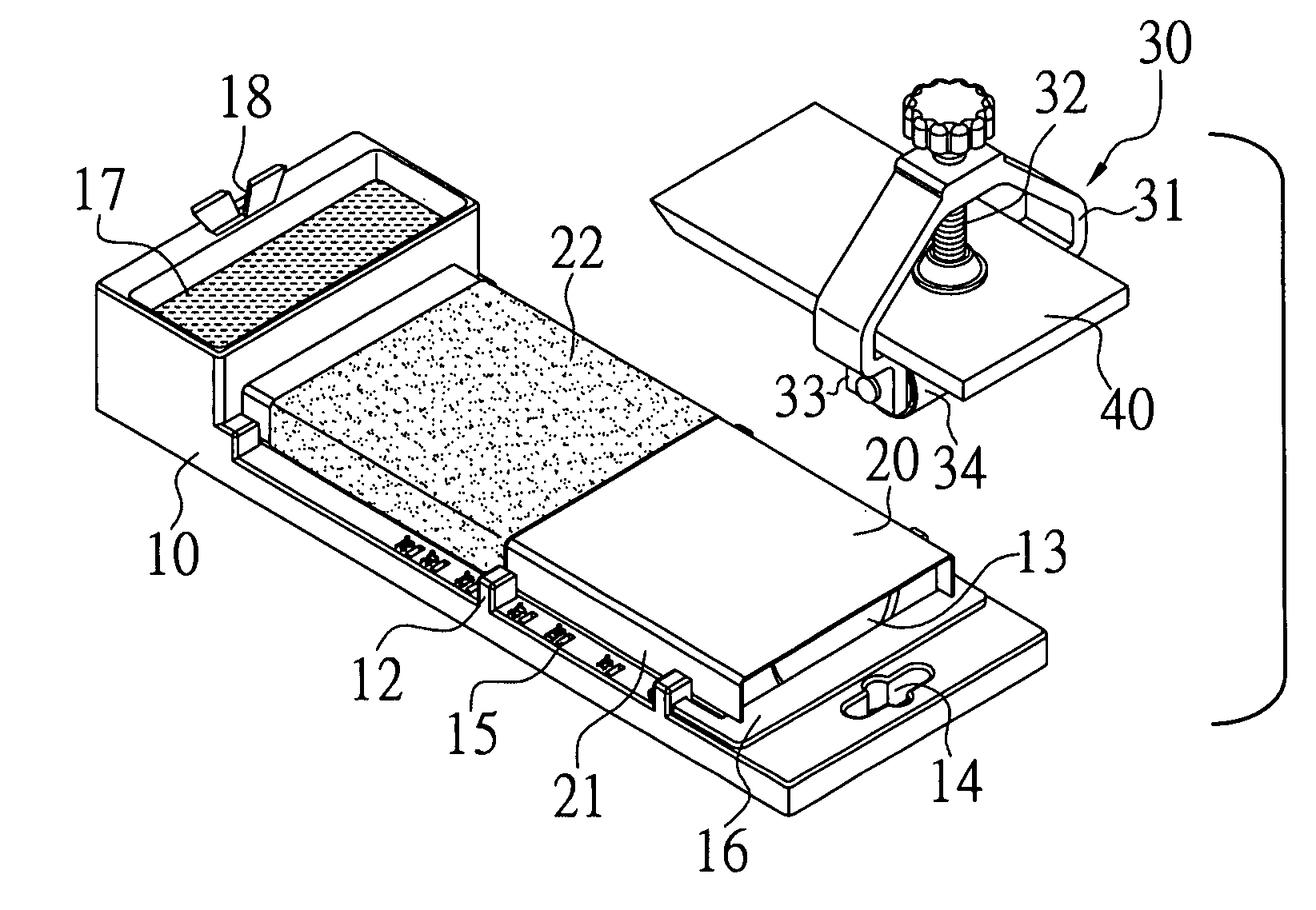
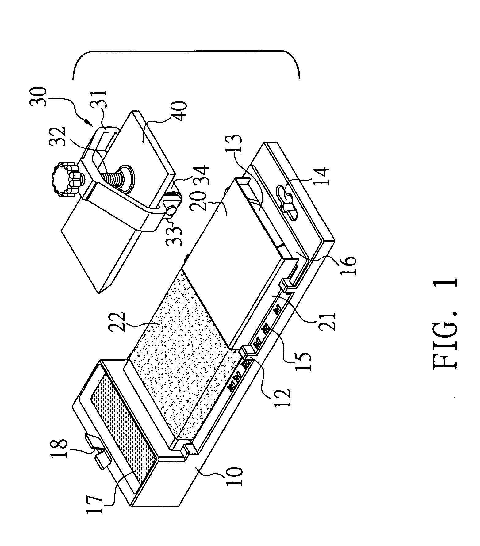
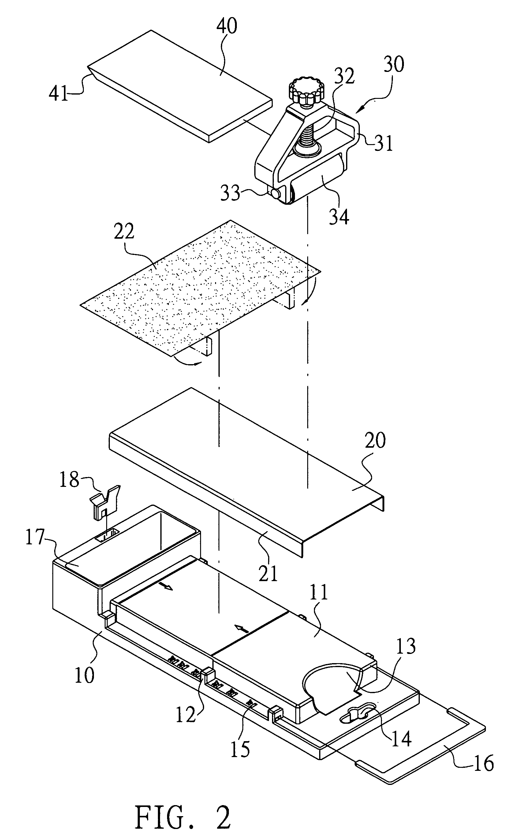
[0029]Referring to FIGS. 1 through 8, a first preferred embodiment of the present invention is essentially comprised of a plastic base (10) injection molded, a mobile base plate (20), and a cutter holder (30). A rectangular deck is disposed on top of the base (10), multiple positioning bits (12) are provided on both sides of the deck (11) and a proper spacing is reserved between each positioning bit (12) and the side of the deck (11) to limit the mobile base plate (20) covering upon the deck (11) in position. A gap (13) is reserved at one end of the deck (11) to facilitate the removing of the mobile base plate (20), and an eyelet (14) is provided on the base (10) at a position close to the gap (13) to facilitate hanging the grinder when not in use. Multiple slots (15) are provided to the base on both sides of the deck (11) to receive insertion of an angle adjustment plate (16) to secure the grinding angle of the cutter. When not required, the angle adjustment plate (16) is stored in...


PUM


Abstract

An innovative cutter-grinder comprised of a base, a cutter holder, and a mobile base plate; the base plate being mounted with emery cloth before being placed on a deck of the frame to secure the emery cloth and allow easy replacement of the emery cloth; the cutter holder adapted with a roller at bottom retaining a blade for the user to hold the cutter holder to roll back and forth on the base plate to grind the cutter against the emery cloth; and an angle set plate being inserted onto slots respectively provided on both sides of the deck allowing the adjustment of the grinding angle.

Description

BACKGROUND OF THE INVENTION[0001](a) Field of the Invention[0002]The present invention is related to an innovative cutter-grinder, and more particularly to one that allows safe grinding and adjustment of the angle of the blade of the cutter to be ground while maintaining good grinding quality.[0003](b) Description of the Prior Art[0004]Whereas after having been used for a certain time, the blade or the cutting edge of a cutter, e.g., the stock of a plane, tends to get worn out or dulled; a grinder or a grindstone is usually needed to restore the blade to its sharp status.[0005]However, inconsistent grinding quality due to failure in maintaining a firm contact between the blade and the surface of the grinder has been always the biggest problem found with the conventional grinder or grindstone. Furthermore, holding the cutter to engage in reciprocal grinding motion increases the chance of contacting the grinder and the blade, resulting in safety concerns of getting one's hand cut.SUMM...

Claims


Application Information

Patent Timeline
IPC IPC(8): B24B25/00B24B19/00
CPCB24D15/06
Inventor LIN, KUN-MENG
Owner LIN KUN MENG
Why Eureka
Try Eureka