Brushless motor for partable electronic equipment with wire treatment technique of coils

a brushless motor and electronic equipment technology, applied in the direction of dynamo-electric machines, electrical devices, windings, etc., can solve the problems of insufficient space around the terminal, the method is not applicable to a small, high-density motor, etc., to achieve the effect of reducing environmental pollution, avoiding solder, and not degrading the quality of the electrical connection portions

Inactive Publication Date: 2006-09-12
PANASONIC CORP
View PDF20 Cites 4 Cited by
  • Summary
  • Abstract
  • Description
  • Claims
  • Application Information

AI Technical Summary

Benefits of technology

[0009]Thus, the present invention has an object to provide a wire treatment technique which can make electrical connection without using a soldering material even when a terminal is used but a sufficient space cannot be obtained around the terminal in a brushless motor, thereby achieving a small brushless motor which causes little environmental pollution and prevents reheating of reflow mounting or the like from degrading the quality.
[0012]With this configuration, since all the electrical connection portions ranging from the end of the coil to the power supply terminal are joined by welding, or since the end of the coil is connected to the terminal by winding and then the end is joined by arc welding, it is possible to obtain a reliable motor which can eliminate solder on the electrical connection portions with little environmental pollution and does not degrade the quality of the electrical connection portions even in the case of severe temperature environments for mounting and use. Moreover, to make electrical connection, means of caulking, crimping, screwing, and so on are available in addition to soldering and welding. In each of these means, a connecting structure occupies a large space. Unlike these means, welding makes the connecting structure to occupy a small space equivalent to a space required by soldering. Hence, it is possible to provide a small and reliable brushless motor.

Problems solved by technology

However, the fusing method requires a large vacant space around the terminal 121.
Therefore, this method is not applicable to a small and high-density motor which does not have a sufficient space around a terminal.

Method used


Image

  • Brushless motor for partable electronic equipment with wire treatment technique of coils
  • Brushless motor for partable electronic equipment with wire treatment technique of coils
  • Brushless motor for partable electronic equipment with wire treatment technique of coils

Examples


embodiment 1

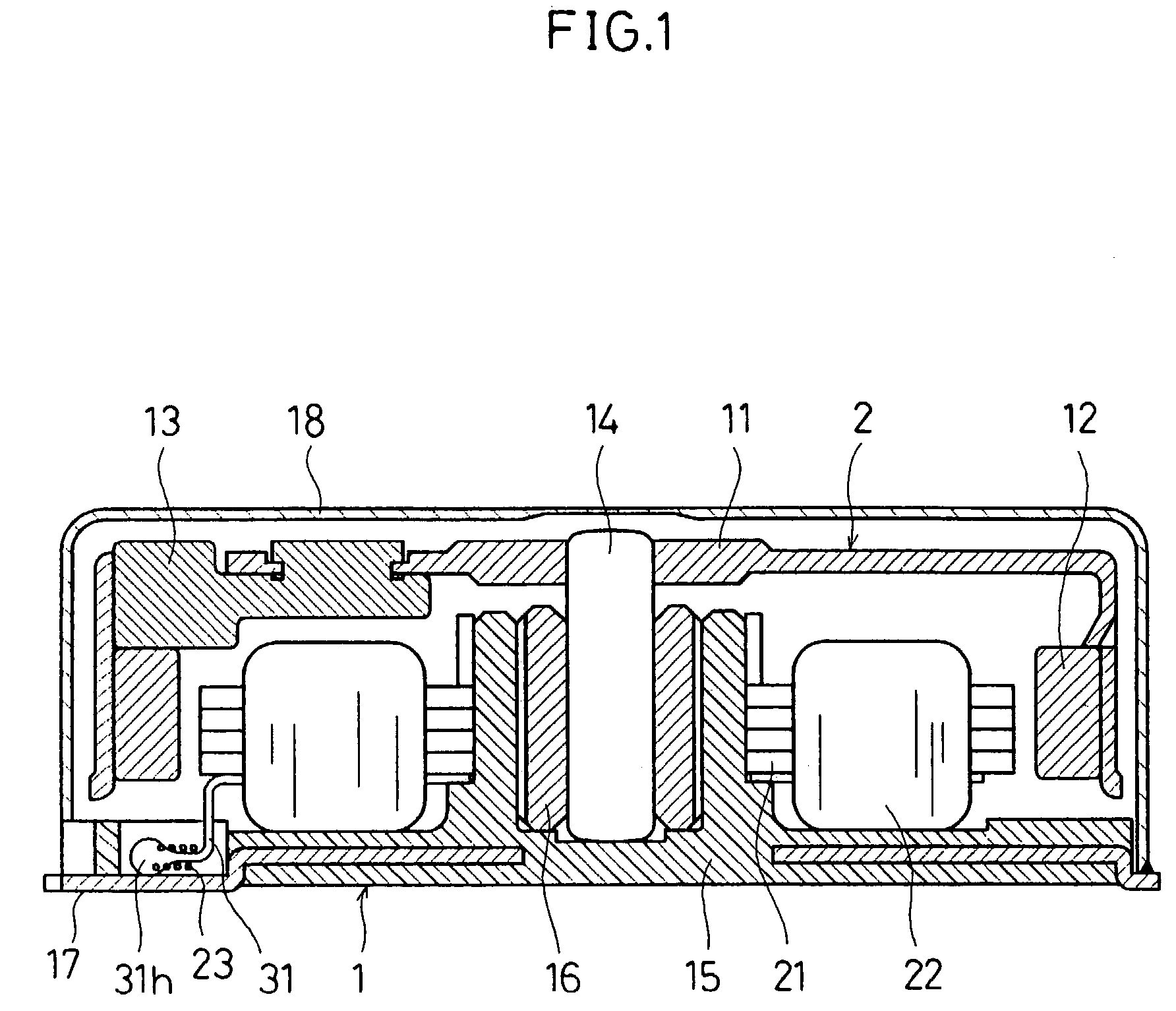
[0032]For example, a motor shown in FIGS. 1 to 7 is a brushless motor which is extremely small and thin with an external diameter of about 10 mm. Such a motor is used for vibration alarm in a mobile phone and so on. In FIG. 1, the motor is constituted by a stator (non-rotating part) 1, a rotor (rotary part) 2, and a cover 18. The rotor 2 has a rotor frame 11 as a main body, and a ring-shaped magnet 12 is attached to the inside of the rotor frame 11. An eccentric weight 13 is attached to the rotor frame 11. The rotor frame 11 rotates around a shaft 14 mounted at the center of the rotor frame 11.

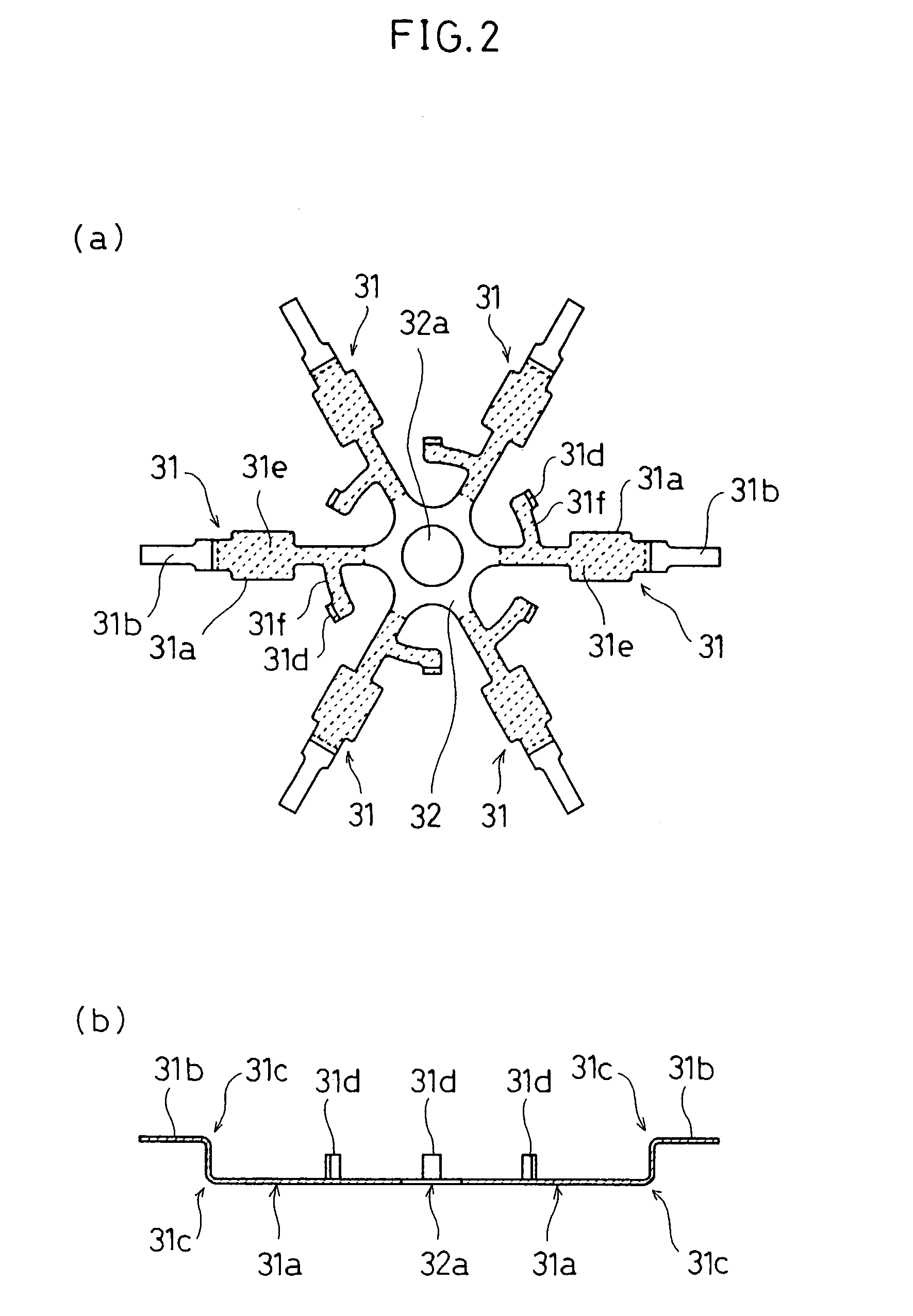
[0033]The stator 1 has a motor base 15 as a main body. A winding assembly composed of a core 21, coils 22, and terminals 31 is mounted on the motor base 15, and a metal 16 for supporting the shaft 14 is further mounted at the center of the motor base 15. Coil ends 23 are connected to power supply terminals 17 of the motor base 15. Moreover, as described above, the shaft 14 of the rotor 2 is ro...

embodiment 2

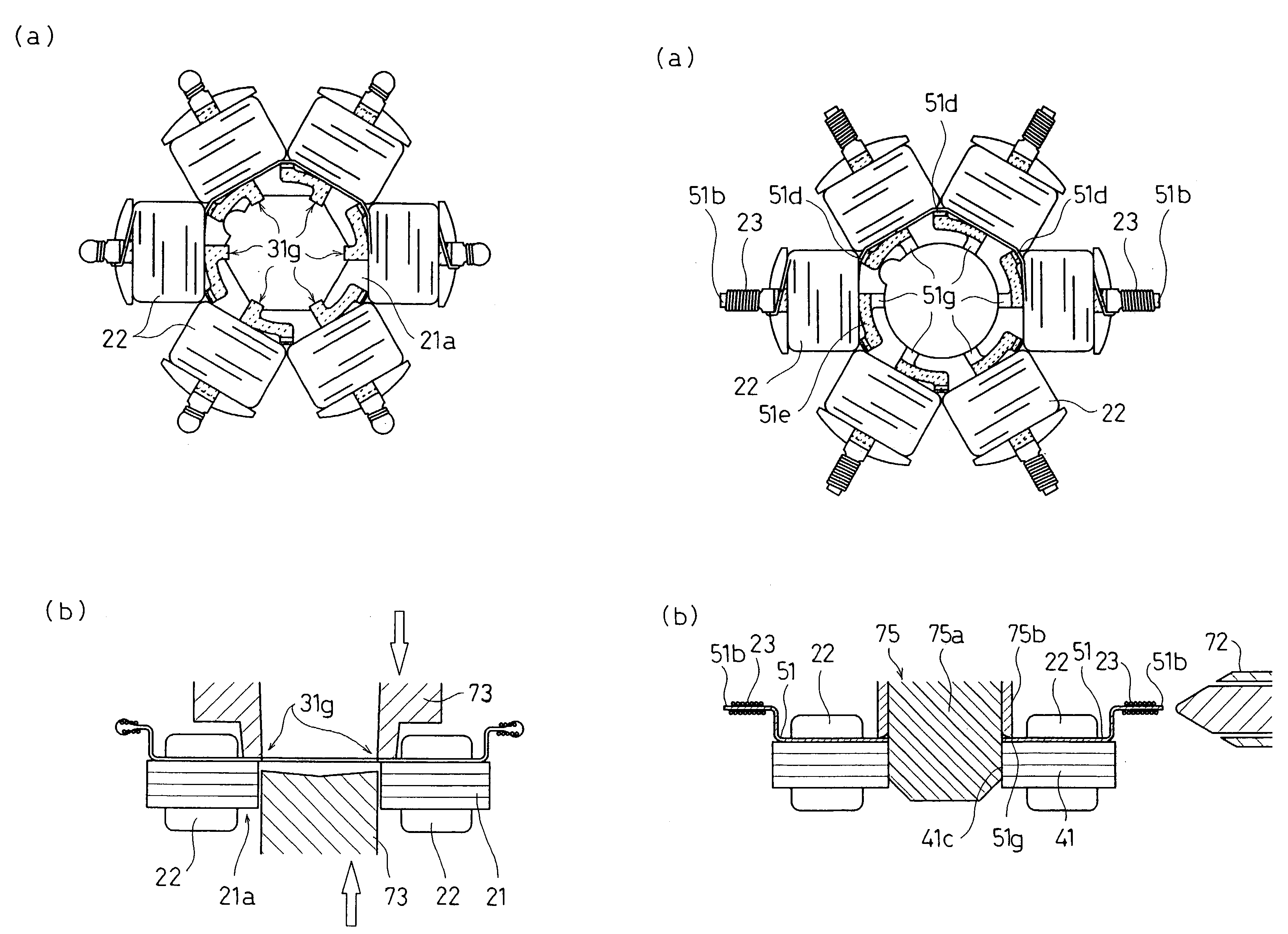
[0058]Referring to FIGS. 8(a) and 8(b) to 10(a) and 10(b), the following will discuss Embodiment 2 of the present invention. In Embodiment 2, the connecting structure of terminals 51 is changed from that of Embodiment 1 and the manufacturing process is changed accordingly. In the following description, drawings and explanations which are redundant or the same as Embodiment 1 will be omitted.

[0059]FIGS. 8(a) and 8(b) shows the shapes of the terminals 51. The six terminals 51 are arranged radially and are integrally connected to one another via a frame-shaped connecting member 52 which is placed outside the terminals 51. On each of the terminals 51, a base portion formed inside along the radial direction is a holding portion 51a which is overlaid on a salient pole of a core, and an end formed outside along the radial direction is a coil end connection portion 51b. Then, as described above, the coil end connection portions 51b reconnected via the connecting member 52 and maintain their...


PUM


Abstract

A brushless motor, comprising a rotor having a magnet, a coil for generating a magnetic field for drivingly rotating the rotor, and a power supply terminal for supplying a power to the coil from outside, wherein all electrical connection parts ranging from the power supply terminal to the end of the coil are connected to each other through welded parts.

Description

TECHNICAL FIELD[0001]The present invention mainly relates to a small brushless motor suitably used for portable electronic equipment and a method of manufacturing the same, and particularly concerns a wire treatment technique of its coil.BACKGROUND ART[0002]In a process of connecting the ends of coils to external power supply terminals in a small brushless motor, in general, wire treatment is performed using terminals and a treated part is soldered to have electric conduction.[0003]For instance, a representative example is disclosed in JP-A-6-46543. In this example, a core has a plurality of salient poles extending radially from a ring part and coils are wound around the salient poles. Further, slots between the salient poles have terminals, and the ends of coils are connected to the terminals by winding. The terminals have coil end winding portions which are formed so as to be bent in the axial direction of the core and can be soldered onto external power supply terminals, each bei...

Claims


Application Information

Patent Timeline
Patent Type & Authority Patents(United States)
IPC IPC(8): H02K11/00H02K3/52
CPCH02K3/522H02K2211/03
Inventor YOSHIDA, SHIGERUFUKUOKA, KODOKUMOI, MASAFUMIKUYAMA, KOJI
Owner PANASONIC CORP
Why Eureka
Try Eureka