
Image forming apparatus and control method therefor

a technology control method, which is applied in the field can solve the problems of reducing print speed to degrade the productivity unable to cope with an increase in the operating speed of image forming apparatus, and different images on the front and back surfaces of recording sheets, etc., to achieve accurate correction of magnification without degrading the quality of formed images, reduce productivity, and increase the operating speed of the apparatus

Inactive Publication Date: 2012-09-11
CANON KK
View PDF13 Cites 2 Cited by
  • Summary
  • Abstract
  • Description
  • Claims
  • Application Information

AI Technical Summary

Benefits of technology

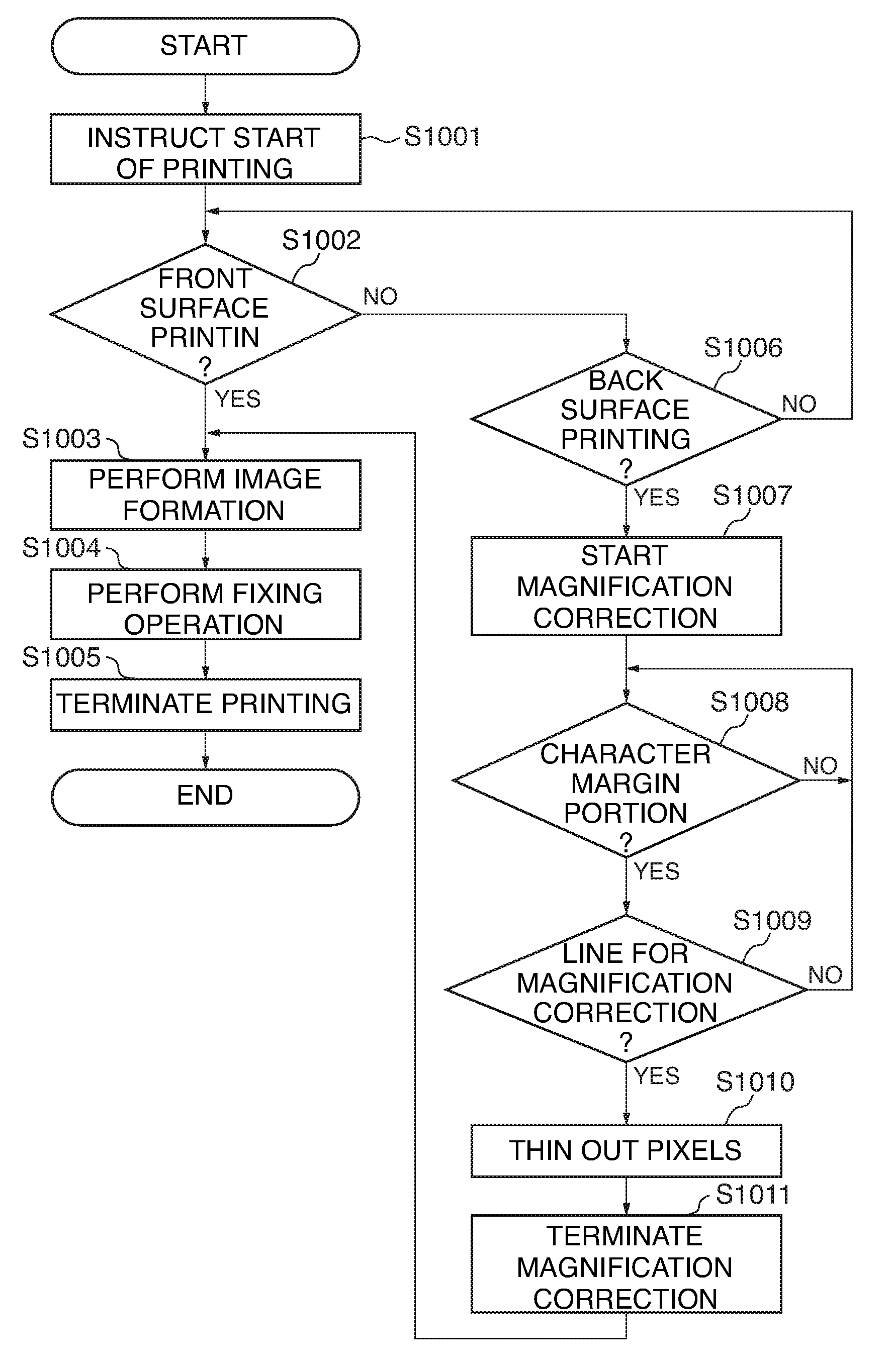
The present invention provides an image forming apparatus that can accurately correct the magnification of an image without degrading the quality of the formed image or reducing productivity. This is achieved by separating the image data into different areas and performing magnification correction on those areas. The apparatus can also determine whether the image data is of a character portion, a margin portion, or a background portion and perform the magnification correction accordingly. Additionally, the apparatus can calculate the expansion / contraction ratio of the recording medium based on the size of the recording medium before and after the image is heat-fixed on it and perform the magnification correction based on this ratio. The invention also provides a method for controlling the image forming apparatus.

Problems solved by technology

This causes the problem that the images on the front surface and back surface of the recording sheet are different in size.
This causes a reduced print speed to degrade productivity of the image forming apparatus, when a sheet-to-sheet interval (conveying intervals of sheets which are conveyed to the transfer position) is short.
Further, it is necessary to control the sheet-to-sheet interval such that a time period taken before the scanning speed becomes stable is ensured, which makes it impossible to cope with an increase in the operating speed of the image forming apparatus.
Further, a change in the image clock for transferring the image data is can only corrects the magnification of the image data in a main scanning direction (direction orthogonal to the image reading direction).
In this case, the rotational speed of the scanner motor is switched, and hence, similarly to the above, there arises the problem that the productivity is lowered due to a decreased in the print speed, and it is impossible to cope with an increase in the operating speed of the image forming apparatus.

Method used


Image

  • Image forming apparatus and control method therefor
  • Image forming apparatus and control method therefor
  • Image forming apparatus and control method therefor

Examples


Embodiment Construction

[0041]The present invention will now be described in detail below with reference to the accompanying drawings showing preferred embodiment thereof.

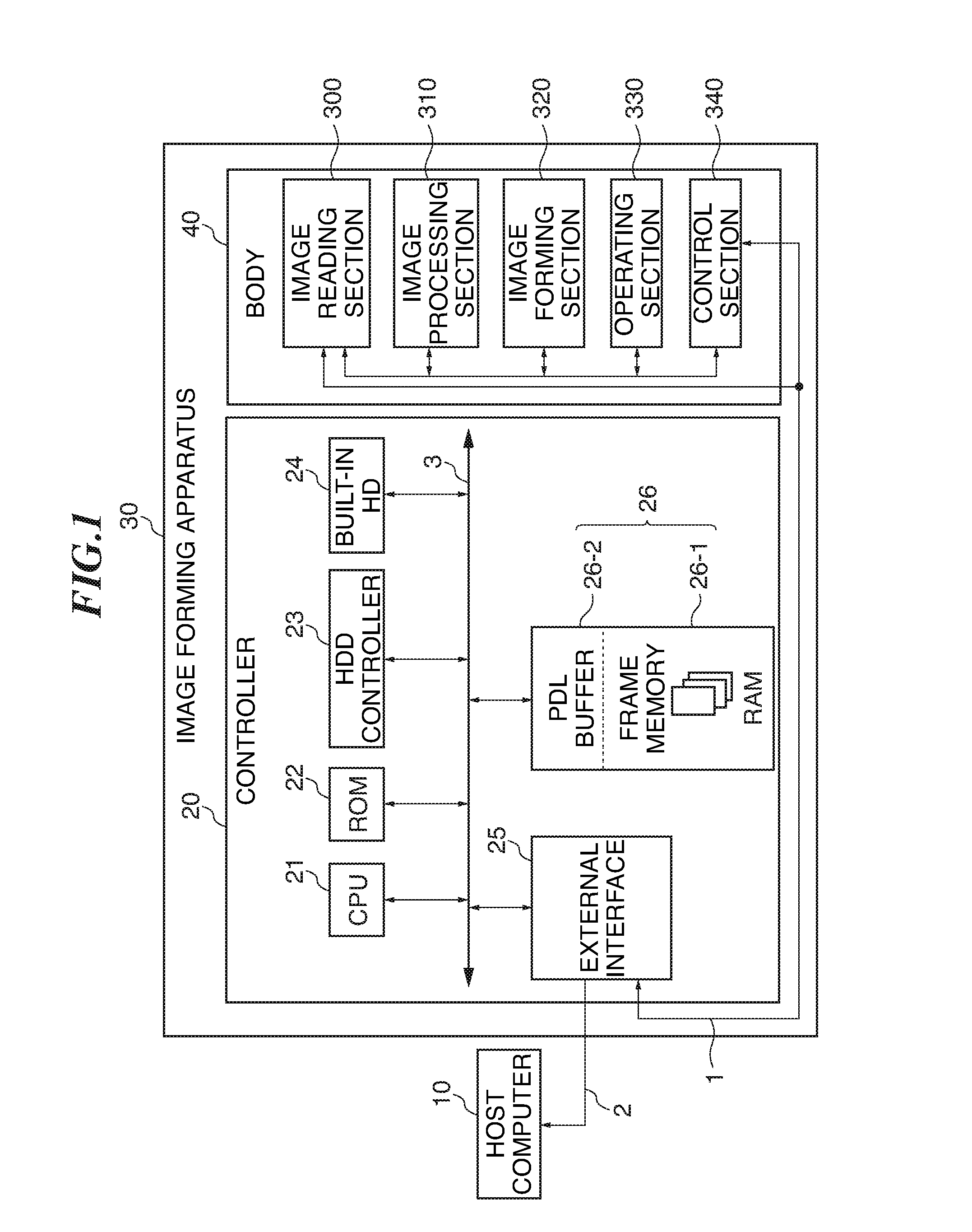
[0042]FIG. 1 is a block diagram of an image processing system according to a first embodiment of the present invention.

[0043]Referring to FIG. 1, the image processing system is comprised of an image forming apparatus (image output apparatus) 30 including a main unit 40 and a controller 20, and a host computer 10. The main unit 40 and the controller 20 of the image forming apparatus 30 are connected to each other by a cable 1, and the controller 20 and the host computer 10 thereof are connected to each other by a cable 2. It should be noted that any of general-purpose cables, such as parallel cables, SCSI (Small Computer System Interface) cables, serial cables, and network cables, and dedicated cables may be used for the cables 1 and 2.

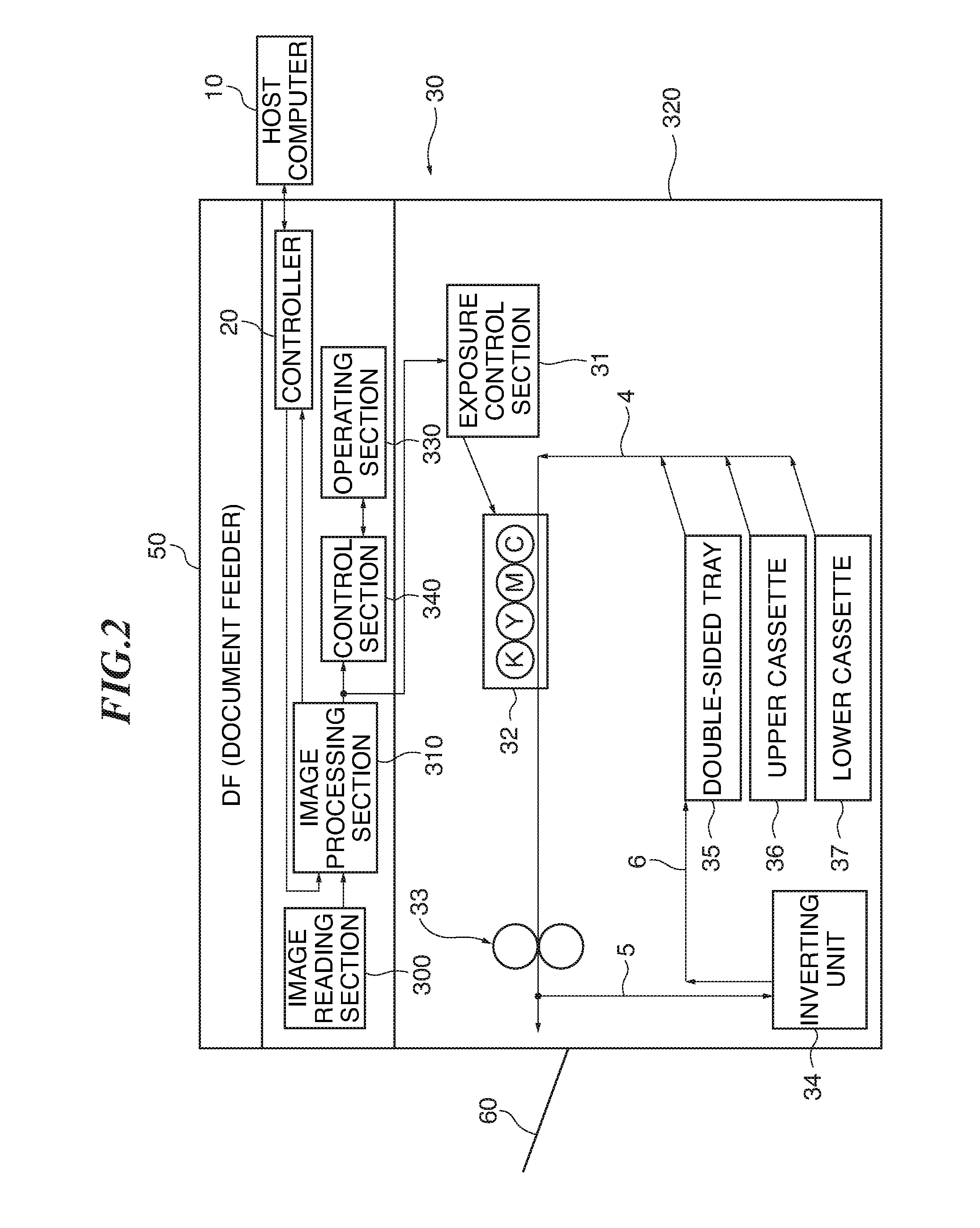
[0044]The image forming apparatus 30 is comprised of an image reading section 300, an image processing se...


PUM


Abstract

An image forming apparatus image which is capable of accurately correcting the magnification of an image without degrading the quality of the formed image or reducing productivity, to thereby make it possible to cope with an increase in the operating speed of the apparatus. The image forming apparatus is comprised of an image processing section having an image area-separating section, and an image forming section having an exposure control section. The image area-separating section separates image data into at least two kinds of areas. The exposure control section performs magnification correction on at least one area of the image data separated by the image area-separating unit.

Description

BACKGROUND OF THE INVENTION[0001]1. Field of the Invention[0002]The present invention relates to an image forming apparatus that performs image formation by an electrophotographic method, and a control method therefor.[0003]2. Description of the Related Art[0004]Conventionally, in the field of an electrophotographic image forming apparatus that performs image formation by executing the steps of charging, exposing, developing, transferring, and fixing, a technique (heat fixing method) is known in which an unfixed toner image transferred onto a recording sheet is heated and fused for fixing. The heat fixing method include not only a sheet heater method and an infrared lamp method, but also a fixing roller method, which is currently most widely used, and an IH (Introduction Heating) fixing method.[0005]In an image forming apparatus that fixes a toner image on a recording sheet by the above heat fixing method, the recording sheet shrinks after the toner image has been fixed, since moist...

Claims


Application Information

Patent Timeline
Patent Type & Authority Patents(United States)
IPC IPC(8): H04N1/393
CPCG06K15/1204G06K2215/0057
Inventor KINOSHITA, HIDEHIKO
Owner CANON KK
Learn More