Current transformer

a current transformer and transformer technology, applied in the direction of transformers/inductance coils/windings/connections, inductances, instruments, etc., can solve the problems of increasing the price of rogowski coils, increasing the error at the time of current measurement, and difficult to meet the above-mentioned conditions

Inactive Publication Date: 2006-09-12
KK TOSHIBA
View PDF8 Cites 77 Cited by
  • Summary
  • Abstract
  • Description
  • Claims
  • Application Information

AI Technical Summary

Benefits of technology

[0020]According to one aspect of the invention, there is provided a current transformer, including a Rogowski coil, having an opening at the center in which a conductor penetrates, comprising, (a) a printed circuit board having a plurality of layers forming at least first to fourth circuit board surfaces including a circuit board top surface, a circuit board bottom surface and circuit board conducting internal surfaces between the circuit board top surface and the circuit board bottom surface, (b) a plurality of radial metal foils, each metal foil radiating from a center that is approximately the center of the opening, mounted on the first to fourth circuit board surfaces, (c) a first winding formed by electrically connecting metal foils on the first and second circuit board surfaces with first plated through holes penetrating the first and second circuit board surfaces in a thickness direction of the printed circuit board, (d) a second winding formed by electrically connecting metal foils on the third and fourth circuit board surfaces with second plated through holes penetrating the third and fourth circuit board surfaces in a thickness direction of the printed circuit board, (e) a first return circuit line electrically connected with the first winding in series, (f) a second return circuit line electrically connected with the second winding in series, wherein a pair of the first winding and the first return circuit line and a pair of the second winding and the second return circuit line are electrically connected in series.

Problems solved by technology

However, when manufacturing the Rogowski coil 1 as shown in FIG. 11, it is technically difficult to satisfy the above-mentioned condition (a), that is, to wind the winding 2 to the core 6 while keeping a constant winding interval.
Although a fixed winding interval can be maintained by preparing slots or projections to the core 6 for fixing position of the winding 2, a special core and winding machine is necessary for this preparation, and thus increases the price of the Rogowski coil which becomes very expensive.
This makes it easier for the Rogowski coil to be influenced by an external magnetic field, and this gives rise to an error at the time of current measurement increases.
Since this voltage is unrelated to the primary current which should originally be measured, it causes a measurement error.
When applying the Rogowski coil 1 to an actual electric power distribution main circuit equipment or substation main circuit equipment, it is impossible to completely eliminate the above-mentioned factors.
In addition, since usually an actual magnetic flux Φ due to the external magnetic field is not uniform, the influence becomes still more complicated.
However, in the common Rogowski coil 1 shown in FIG. 14, it is difficult to manufacture while controlling the area the return circuit line 3 surrounds being constant, thus it is very difficult to avoid the influence of an external magnetic field.
Now, although the influence of the external magnetic field to the Rogowski coil has been explained so far, another problem is explained here.
That is, although it has been stated that the influence of the external magnetic field can be considerably reduced by adopting the Rogowski coil as shown in FIG. 15, there is still a problem that the common Rogowski coil shown in FIG. 14 cannot be simply replaced with the Rogowski coil shown in FIG. 15.
However, for the Rogowski coil shown in FIG. 15, there is a physical limit in a number of turns of a coil and a size of cross section of one turn coil in the winding, because of a structural reason that the coil winding is composed of the metal foils formed on the printed circuit board.
Although depended on the size of the printed circuit board and the width of the metal foil, a number of turns of a coil is limited to at most one thousand, and the cross section of one turn coil in the winding is restricted due to the fact that the manufacturing limit of thickness of the printed circuit board is at most 5 to 6 millimeters.
Though it is assumed that ten sheets of the Rogowski coils are connected in series, the secondary output voltage is about 1 V / kA, and, from a viewpoint on withstanding transmission noise, it is difficult to transmit an accurate analog-voltage signal to a main control building of an electric power installation.

Method used


Image

  • Current transformer
  • Current transformer
  • Current transformer

Examples


first embodiment

[0043](First Embodiment)

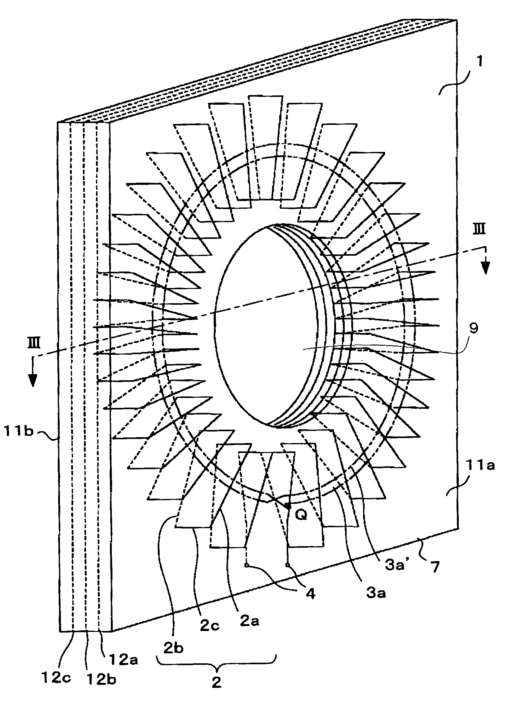
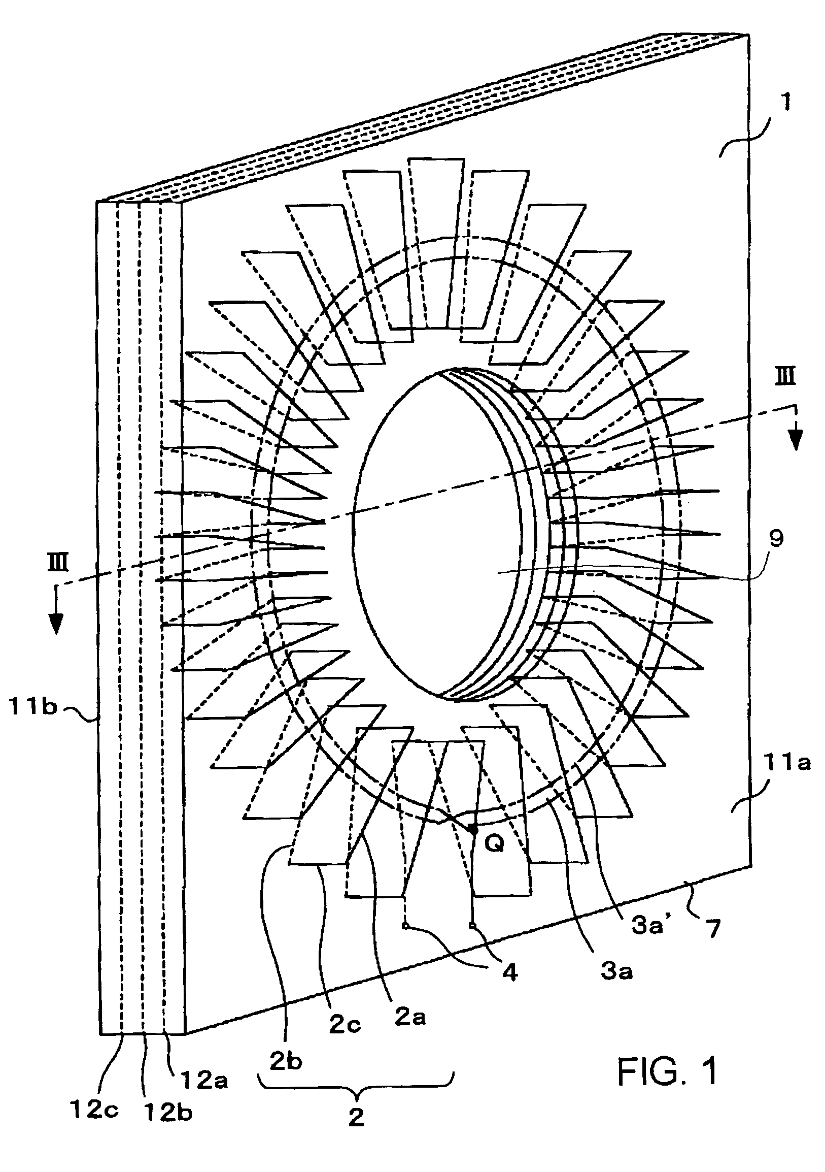
[0044]FIGS. 1, 2 and 3 show a Rogowski coil applied to a current transformer in accordance with a first embodiment of this invention. In this embodiment, firstly, a case forming doubled windings to a printed circuit board of multiple-layer composition with five surfaces is explained. In FIG. 1, a printed circuit board 7 is of multiple-layer composition with five surfaces consisting of a circuit board top surface 11a, a circuit board bottom surface 11b, and three circuit board conducting internal surfaces 12a, 12b, and 12c put between the circuit board top surface 11a and the circuit board bottom surface 11b. The printed circuit board 7 has a circular opening 9, in a center portion, which is penetrated by a conductor (not illustrated) in which alternating current of a main circuit passes.

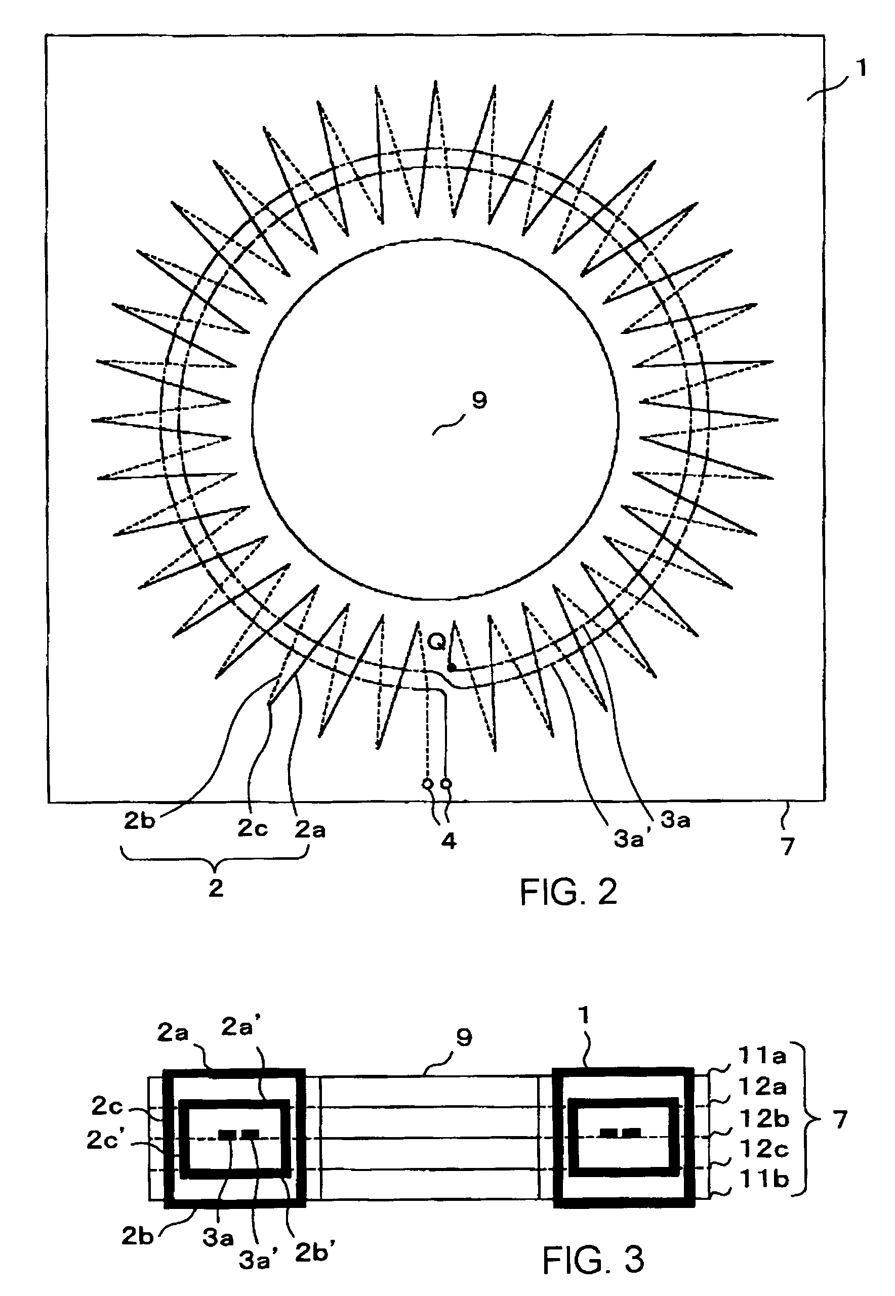
[0045]FIG. 2 is an outline front view of the printed circuit board 7 from a direction of central axis of the opening 9. FIG. 3 is a sectional view along with the line III—III ...

second embodiment

[0056](Second Embodiment)

[0057]FIGS. 5, 6 and 7 show a Rogowski coil applied to a current transformer in accordance with a second embodiment of this invention. In this embodiment, firstly, a case forming fourfold windings to a printed circuit board of multiple-layer composition with eight surfaces is explained. In FIG. 5, a printed circuit board 7 is of multiple-layer composition with eight surfaces consisting of a circuit board top surface 11a, a circuit board bottom surface 11b, and six circuit board conducting internal surfaces 12a, 12b, 12c, 12d, 12e and 12f put between the circuit board top surface 11a and the circuit board bottom surface 11b. The printed circuit board 7 has a circular opening 9, in a center portion, which is penetrated by a conductor (not illustrated) in which alternating current of a main circuit passes.

[0058]FIG. 6 is an outline front view of the printed circuit board 7 from a direction of central axis of the opening 9. FIG. 7 is a sectional view along with ...

third embodiment

[0064](Third Embodiment)

[0065]FIG. 8 shows a Rogowski coil applied to a current transformer in accordance with a third embodiment of this invention. In this embodiment, firstly, a case forming fourfold windings to a printed circuit board of multiple-layer composition with eight surfaces is explained. In FIG. 8, a printed circuit board 7 is of multiple-layer composition with eight surfaces consisting of a circuit board top surface 11a, a circuit board bottom surface 11b, and six circuit board conducting internal surfaces 12a, 12b, 12c, 12d, 12e and 12f put between the circuit board top surface 11a and the circuit board bottom surface 11b. The printed circuit board 7 has a circular opening 9, in a center portion, which is penetrated by a conductor (not illustrated) in which alternating current of a main circuit passes.

[0066]As illustrated, radial metal foils 2a-1 are formed on the circuit board top surface 11a (the first surface) in form of a plurality of straight lines radially sprea...


PUM

PropertyMeasurementUnit
thicknessaaaaaaaaaa
voltageaaaaaaaaaa
voltageaaaaaaaaaa

Abstract

A current transformer includes a Rogowski coil, having an opening at the center in which a conductor penetrates, comprising, a printed circuit board having a plurality of layers forming at least first to fourth circuit board surfaces including a circuit board top surface, a circuit board bottom surface and circuit board conducting internal surfaces between the circuit board top surface and the circuit board bottom surface, a plurality of radial metal foils, each metal foil radiating from a center that is approximately the center of the opening, mounted on the first to fourth circuit board surfaces, a first winding formed by electrically connecting metal foils on the first and second circuit board surfaces with first plated through holes penetrating the first and second circuit board surfaces in a thickness direction of the printed circuit board, a second winding formed by electrically connecting metal foils on the third and fourth circuit board surfaces with second plated through holes penetrating the third and fourth circuit board surfaces in a thickness direction of the printed circuit board, a first return circuit line electrically connected with the first winding in series, a second return circuit line electrically connected with the second winding in series, and a pair of the first winding and the first return circuit line and a pair of the second winding and the second return circuit line being electrically connected in series.

Description

CROSS-REFERENCE TO RELATED APPLICATIONS[0001]This application is based upon and claims the benefit of priority from the prior Japanese Patent Application No. 2002-284856 filed on Sep. 30, 2002, the entire contents of which are incorporated herein by reference.BACKGROUND OF THE INVENTION[0002]1. Field of the Invention[0003]This invention relates to a current transformer and current transformer system which are used to measure an alternating current passing in, for example, a main circuit of electric power distribution equipment or substation main circuits equipment, and especially relates to a current transformer and digitalized electronic current transformer system using a Rogowski coil.[0004]2. Description of the Related Art[0005]Generally, a penetrated type current transformer is used in many cases for measuring alternating current passing in electric power distribution equipment, substation main circuit equipment and so on. In a conventional penetrated type current transformer, a...

Claims


Application Information

Patent Timeline
Patent Type & Authority Patents(United States)
IPC IPC(8): H01F27/28H01F38/28G01R15/18H01F5/00H01F17/00H01F38/30
CPCG01R15/181H01F38/30H01F5/003H01F17/0013G01R19/2513
Inventor SAITO, MINORU
Owner KK TOSHIBA
Why Eureka
Try Eureka