Antenna mounting apparatus

a technology for mounting apparatuses and antennas, applied in the field of antenna systems, can solve the problems of increasing the infrastructure equipment required by a wireless network, difficult maintenance, and/or custom-made to fit specific systems, and achieve the effect of increasing friction with the surface of the utility pol

Inactive Publication Date: 2006-09-12
SAMSUNG ELECTRONICS CO LTD
View PDF7 Cites 222 Cited by
  • Summary
  • Abstract
  • Description
  • Claims
  • Application Information

AI Technical Summary

Benefits of technology

[0015]In a further embodiment of the apparatus, at least a portion of a surface of the faceplate capable of engagin...

Problems solved by technology

However, the use of a larger number of smaller cell sites also increases the infrastructure equipment required by a wireless network.
Much of the antenna equipment that has been ins...

Method used


Image

  • Antenna mounting apparatus
  • Antenna mounting apparatus
  • Antenna mounting apparatus

Examples


Embodiment Construction

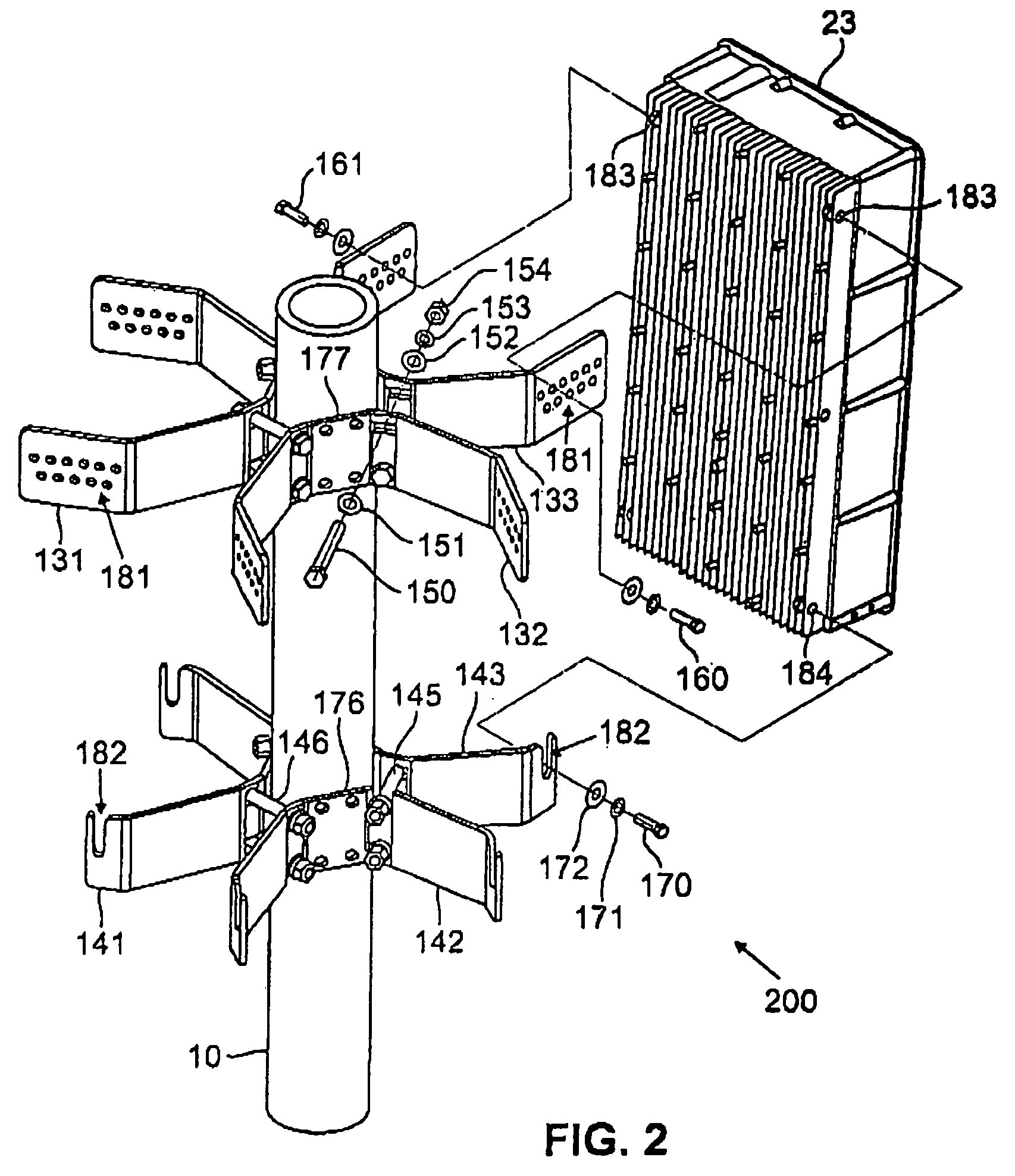
[0024]FIGS. 1 and 2, discussed below, and the various embodiments used to describe the principles of the present invention in this patent document are by way of illustration only and should not be construed in any way to limit the scope of the invention. Those skilled in the art will understand that the principles of the present invention may be implemented in any suitably arranged multi-sector antenna.

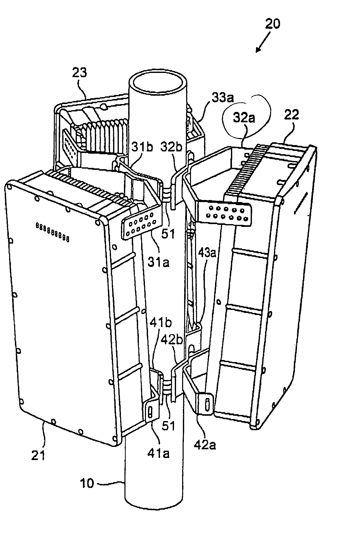
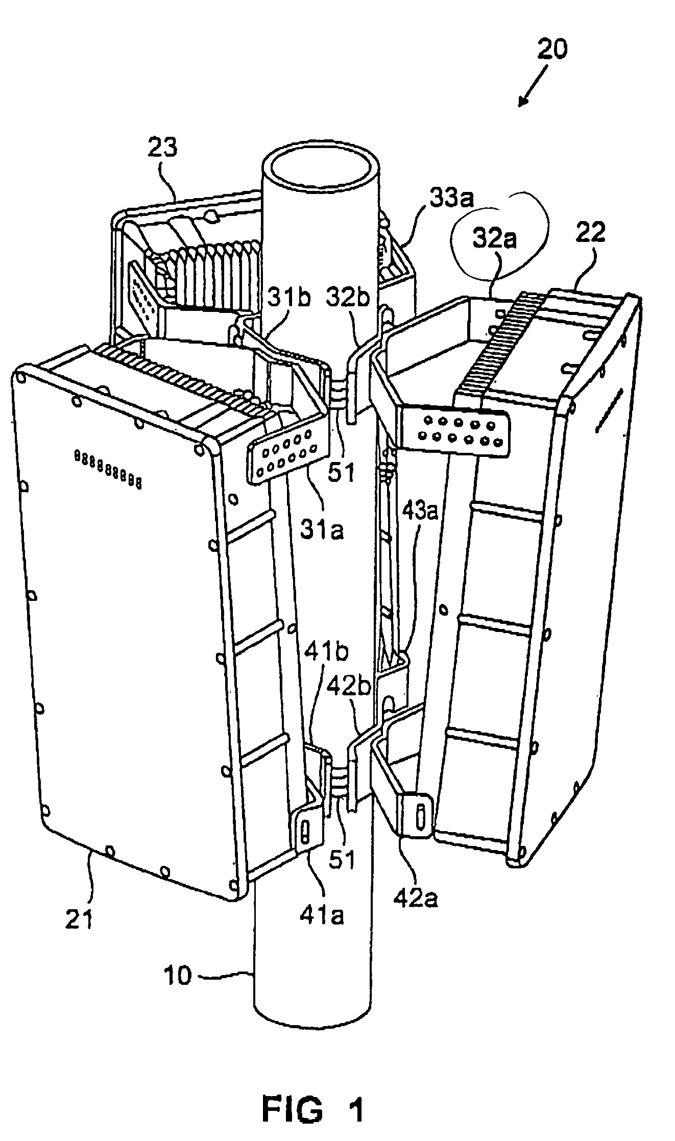
[0025]FIG. 1 illustrates a perspective view of multi-sector antenna system 20 according to one embodiment of the present invention. Multi-sector antenna system 20 comprises three individual sector antennas, namely antenna 21, antenna 22 and antenna 23, mounted on utility pole 10. Multi-sector antenna system 20 is associated with a single base transceiver station (BTS) that serves a single cell site in a wireless network. Each of antennas 21–23 transmits and receives signals in a specified 120° arc around the cell site.

[0026]Antenna 21 is attached to utility pole 10 by means of upper b...


PUM


Abstract

There is disclosed an apparatus for mounting antennas on a utility pole. The apparatus comprises a group of brackets that encircle the utility pole and support the antennas. Each bracket comprises at least one support arm capable of attaching to an antenna and a faceplate that presses against the surface of the utility pole. The apparatus also includes tightening or closure means, such as nut and bolt assemblies, that connect the brackets together. When tightened, the tightening means draw the brackets encircling the utility pole closer together, thereby pressing the faceplates of each bracket more firmly against the utility pole. This clamps the apparatus tightly in place at selected points on the utility pole.

Description

TECHNICAL FIELD OF THE INVENTION[0001]The present invention is directed, in general, to antenna systems and, more specifically, to an apparatus for easily mounting and adjusting an antenna on a pole or similar fixture.BACKGROUND OF THE INVENTION[0002]In recent years there has been a rapid growth in the use of wireless devices, including one-way and two-way pagers, cellular phones, personal communication services (PCS) systems, and personal computers (PCs) equipped with cellular modems or wireless network cards. To support this growth, wireless service providers have dramatically increased the amount and the density of wireless network infrastructure deployed nationwide.[0003]The large number of subscribers and the many applications for wireless communications have created a heavy subscriber demand for RF bandwidth. To maximize usage of the available bandwidth, a number of multiple access technologies have been implemented to allow more than one subscriber to communicate simultaneous...

Claims


Application Information

Patent Timeline
IPC IPC(8): H01Q1/12H01Q1/00
CPCH01Q1/246H01Q1/1228H01Q1/00
Inventor BRUNSON, JAMES S.NGUYEN, HIEP X.
Owner SAMSUNG ELECTRONICS CO LTD
Why Eureka
Try Eureka