Shock mount assembly for attachment of an electronic device to a support structure

a technology of shock-absorbing device and shock-absorbing assembly, which is applied in the direction of machine supports, electric apparatus casings/cabinets/drawers, instruments, etc., can solve the problems of many types of electronic devices, such as optical disk drives and magnetic recording hard disk drives (hdds), which are sensitive to mechanical shock, and achieve the effect of shock-absorbing

Active Publication Date: 2006-09-12
WESTERN DIGITAL TECH INC
View PDF23 Cites 66 Cited by
  • Summary
  • Abstract
  • Description
  • Claims
  • Application Information

AI Technical Summary

Benefits of technology

[0006]The invention is a shock-mount assembly for attachment of an electronic device to a support structure. Two identical assemblies are located on opposite sides of the electronic device and attach it to the support structure. Each shock-mount assembly has a suspension member with a spring-like cantilever beam attached to each end. The cantilever beams are generally planar and have their free ends attached to mounting platforms on the support structure. Damping material is located on the planar surfaces of the cantilever beams between the beams and the mounting platforms. The assembly includes a clamping plate that compresses the damping material between the beams and the mounting platforms when the clamping plate and beams are attached to the support structure. The shock-mount assemblies with the spring-like cantilever beams and the compressed damping material thus act as a highly-damped nonlinear spring system that provides mechanical-shock resistance for the device in a direction perpendicular to the planar beams and high stiffness in a direction parallel to the planar beams.
[0007]The shock-mount assembly may be part of an HDD assembly that includes two shock-mount assemblies attached to the sides of the HDD, with the free ends of the cantilever beams attached generally at the middle of the sides of a frame that generally surrounds the HDD and acts as the support structure. The clamping plate of each shock-mount assembly has a hole or notch at its end for attachment to the frame to provide additional rigidity of the clamping plate and frame. The frame can have attachment and alignment features for a printed-circuit card, which permits the HDD to be readily shock-mounted inside a portable host system, such as an MP3 player, that is typically subjected to mechanical shock during ordinary use.

Problems solved by technology

Many types of electronic devices, such as disk drives, including optical disk drives and magnetic recording hard disk drives (HDDs), are sensitive to mechanical shock, i.e., sudden acceleration or deceleration.

Method used


Image

  • Shock mount assembly for attachment of an electronic device to a support structure
  • Shock mount assembly for attachment of an electronic device to a support structure
  • Shock mount assembly for attachment of an electronic device to a support structure

Examples


Embodiment Construction

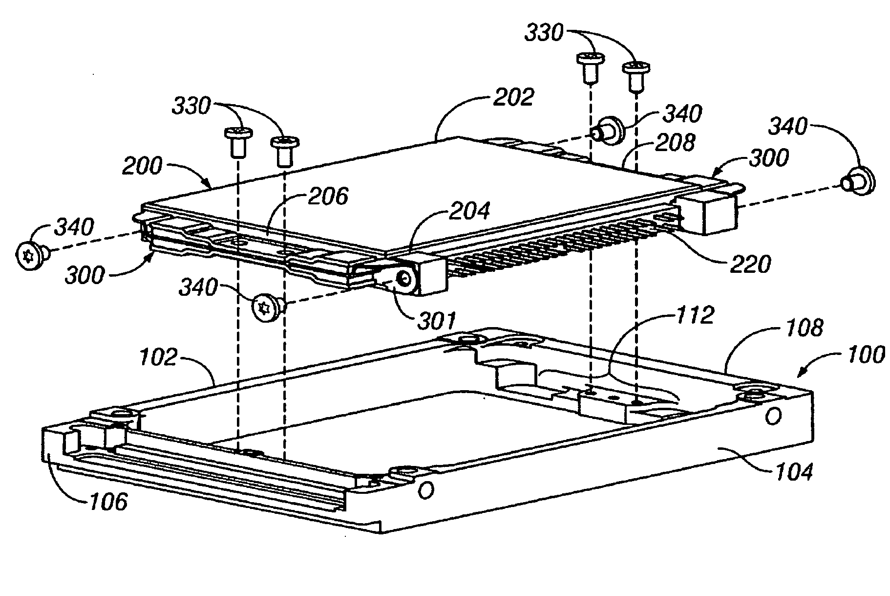
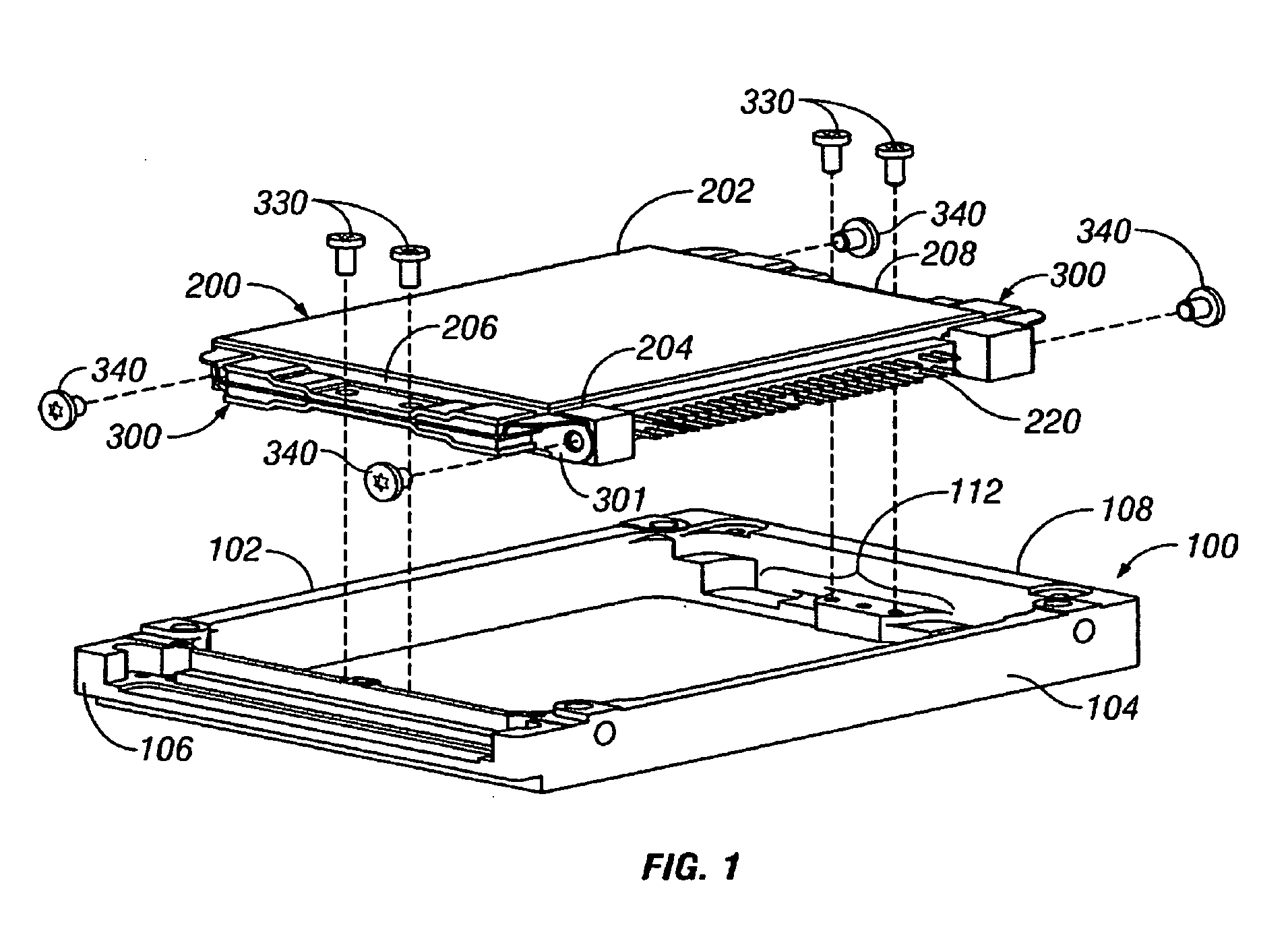
[0015]FIG. 1 is an exploded isometric view showing the relationship between the shock-mount assemblies 300 of this invention and a support structure, represented as a frame 100, and the electronic device, represented as a hard-disk drive (HDD) 200. The support structure (frame 100) has sides 102, 104, a front end 106 and a rear end 108. The frame includes mounting platforms for attachment of the shock-mount assemblies 300, such as platform 112 shown on frame rear end 108. Fasteners, such as screws 330, attach the mount assemblies to the mounting platforms. The electronic device (HDD 200) has sides 202, 204, and ends 206, 208. Each shock-mount assembly 300 is attached to a respective end 206, 208 of the HDD 200 by fasteners, such as screws 340.

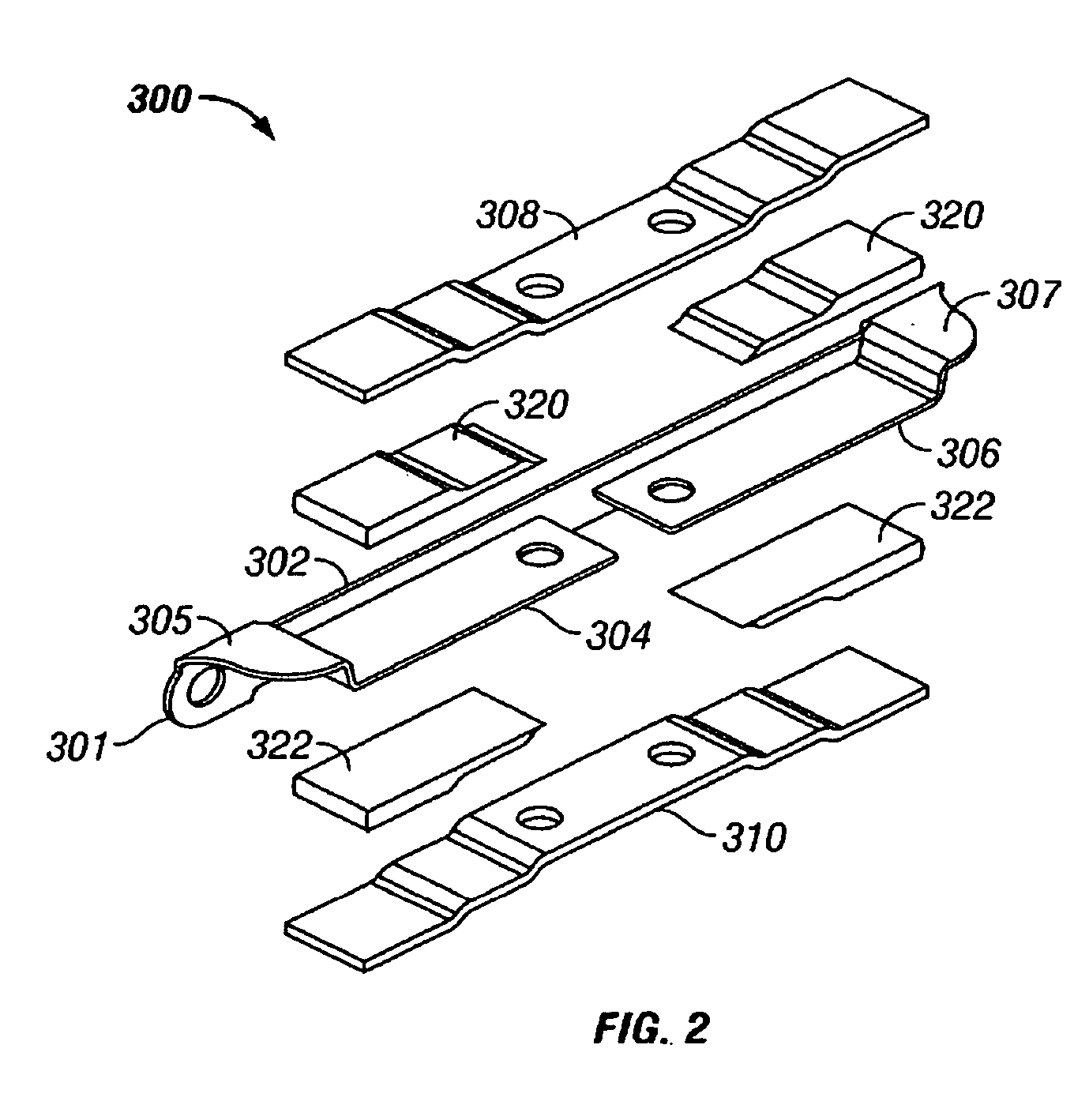
[0016]FIG. 2 is an exploded isometric view of shock-mount assembly 300 and shows a suspension member 301, damping layers 320, 322, and clamping plates 308, 310 that compress the damping layers when the shock-mount assembly is attached to the su...


PUM

PropertyMeasurementUnit
lengthaaaaaaaaaa
dampingaaaaaaaaaa
length L1aaaaaaaaaa

Abstract

A mechanical-shock-mount assembly enables attachment of a mechanical-shock-sensitive electronic device to a support structure. Two identical shock-mount structures are attached and located on opposite sides of an electronic device. Each shock-mount structure has a pair of generally planar spring-like cantilever beams that have their free ends for attachment to the support structure. Damping material is located on the surfaces of the cantilever beams between the beams and clamping surfaces. At least one clamping surface is a plate that compresses the damping material between itself and the beam and / or compresses the damping material between the beam and a surface of the support structure when it is attached to the support structure. This shock-mount structure acts as a highly-damped nonlinear spring system that provides mechanical-shock resistance for the device in a direction perpendicular to the cantilevered beams and high stiffness in a direction in the plane of the beams. If desired, the shock-mounts can be first assembled to the support structure before attaching the device. The support structure can optionally have additional features for attaching other components of the device host.

Description

BACKGROUND OF THE INVENTION[0001]1. Field of the Invention[0002]This invention relates generally to mechanical-shock-mounts or shock absorbers for attachment of mechanical-shock-sensitive electronic devices to support structures.[0003]2. Description of the Related Art[0004]Many types of electronic devices, such as disk drives, including optical disk drives and magnetic recording hard disk drives (HDDs), are sensitive to mechanical shock, i.e., sudden acceleration or deceleration. Disk drives are especially sensitive to shock in a direction perpendicular or normal to the disks. Mechanical-shock-sensitive electronic devices are finding wide use in portable host systems, such as notebook computers, personal digital assistants (PDAs), cell phones, and MP3 music players, all of which experience mechanical shock in ordinary use.[0005]What is needed is a shock-mount assembly for attachment of a mechanical-shock-sensitive electronic device to a support structure, wherein the support structu...

Claims


Application Information

Patent Timeline
Patent Type & Authority Patents(United States)
IPC IPC(8): H05K5/00H05K7/00F16F15/08G11B33/08
CPCG11B33/08F16F15/085
Inventor ALBRECHT, DAVID W.ZENG, QINGHUA
Owner WESTERN DIGITAL TECH INC
Why Eureka
Try Eureka