Optical packet switching apparatus and methods

Active Publication Date: 2006-09-12
F POSZAT HU
View PDF27 Cites 41 Cited by
  • Summary
  • Abstract
  • Description
  • Claims
  • Application Information

AI Technical Summary

Benefits of technology

[0075]When optical packets are provided at different bit-rates on a plurality of input paths, optical packets provided at low bit-rates may be compacted b

Problems solved by technology

Both techniques of optical packet switching mentioned above have however similar problems that are encountered with bandwidth contention and switching of optical packets that are carried over optical paths at different bit-rates.
The problem encountered with switching of optical packets that are carried over optical paths at different bit-rates is independent of bandwidth contention, and in fact occurs both in a case where there is bandwidth contention and in a case where

Method used


Image

  • Optical packet switching apparatus and methods
  • Optical packet switching apparatus and methods
  • Optical packet switching apparatus and methods

Examples


Embodiment Construction

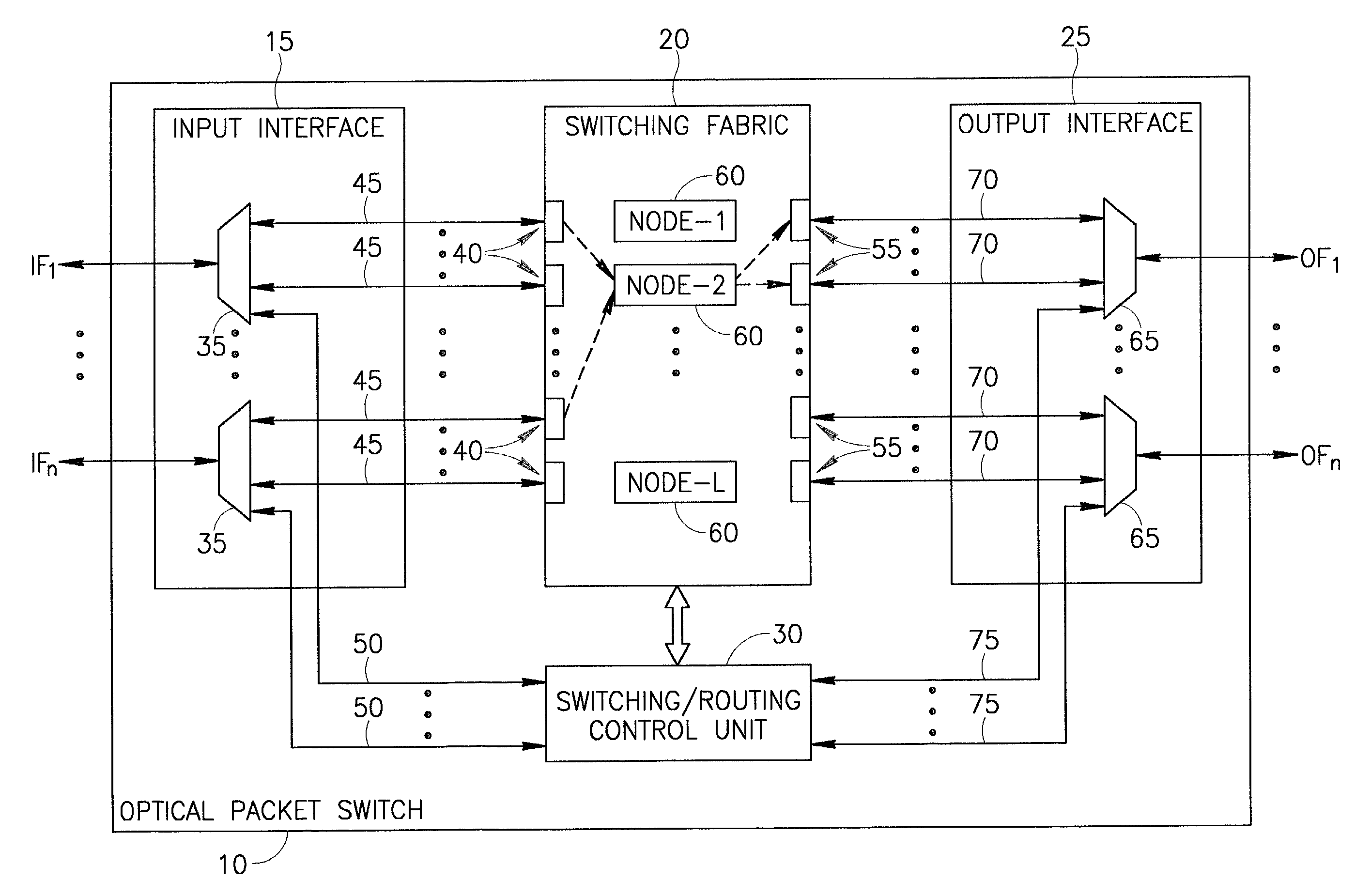
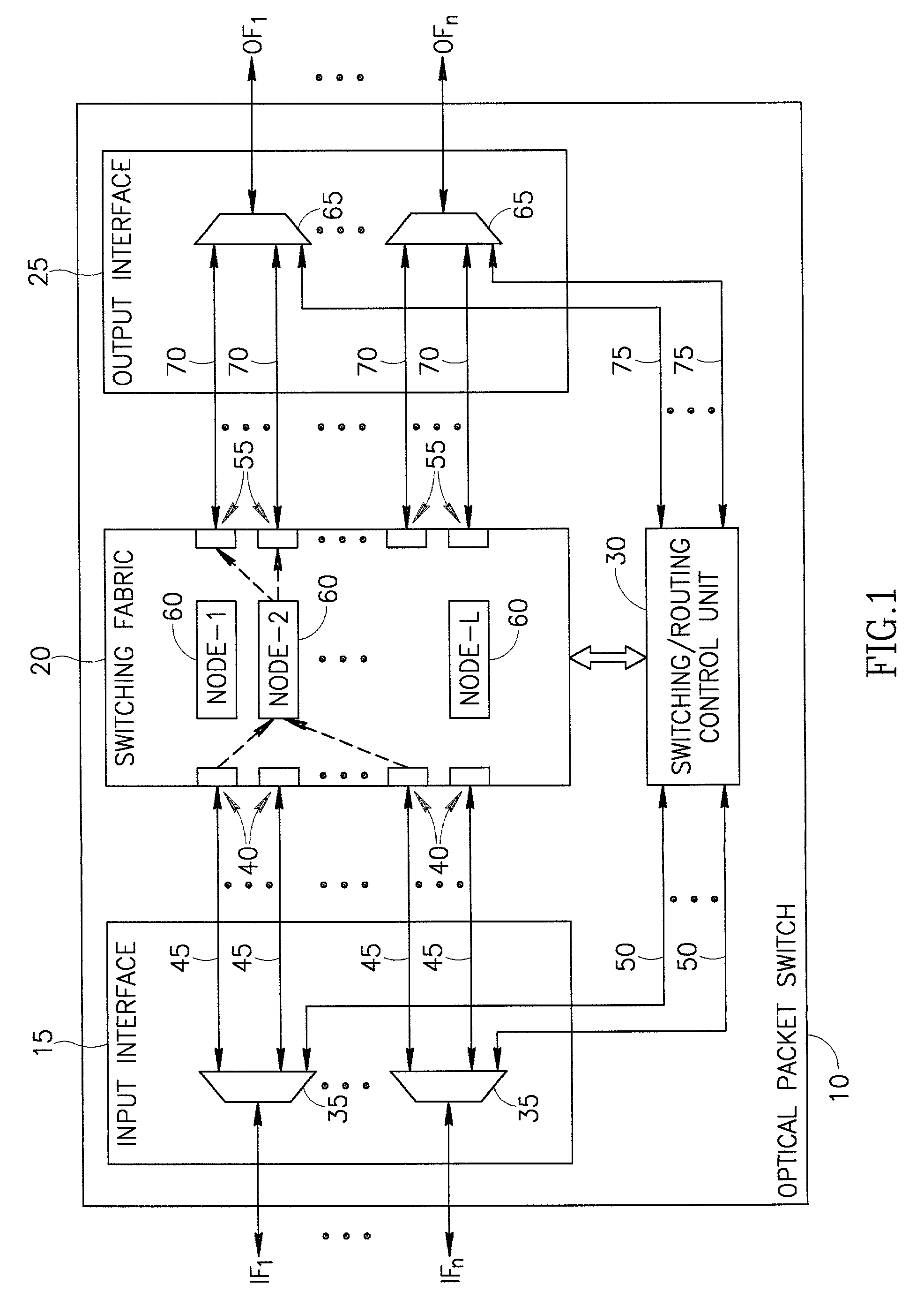
[0126]Reference is now made to FIG. 1 which is a simplified block diagram illustration of a preferred implementation of an optical packet switch 10, the optical packet switch 10 being constructed and operative in accordance with a preferred embodiment of the present invention.

[0127]The optical packet switch 10 preferably includes the following elements: an input interface 15; a switching fabric 20; an output interface 25; and a switching / routing control unit 30.

[0128]The input interface 15 is preferably operatively associated with a plurality of incoming fibers (IFs), such as n incoming fibers IF1, . . . , IFn where n is an integer. The n incoming fibers IF1, . . . , IFn are preferably respectively coupled to n optical demultiplexers 35 in the input interface 15. The n optical demultiplexers 35 are operative to demultiplex optical signals carried by the incoming fibers IF1, . . . , IFn and to provide optical packets carrying information to a plurality of input ports 40 of the switch...


PUM


Abstract

An optical packet switch switches optical packets according to bit-rates at which the optical packets are provided. For example, optical packets that are received at similar bit-rates may be routed to a destination at separate time slots over a single channel wavelength, and optical packets that are received at different bit-rates may be routed to the destination over separate channel wavelengths. When optical packets are provided at different bit-rates on a plurality of input paths, optical packets provided at low bit-rates may be compacted before switching to the destination. Alternatively or additionally, the bit-rates of the optical packets may be balanced before switching to the destination. Bandwidth contention among optical packets may be resolved by polarizing optical packets originating from separate input paths in different polarization directions, and merging optical packets having different polarization directions onto a single switched channel wavelength. Compaction of optical packets may alternatively be employed for resolution of bandwidth contention. Related apparatus and methods are also described.

Description

FIELD OF THE INVENTION[0001]The present invention relates generally to optical communication networks, and more particularly to optical packet switching in optical communication networks.BACKGROUND OF THE INVENTION[0002]The rapid growth of data communications and the deployment of optical communication systems that utilize wavelength division multiplexing (WDM) created a demand for new switching methods. Optical packet switching is considered today a switching method that is particularly suitable for data communications and for optical communication systems that utilize WDM.[0003]There are two main techniques for optical packet switching, and they mainly differ in the structure of optical packets utilized thereby and in switching node operation. The first technique is based on fixed-length packets with synchronous node operation, and the second technique is based on variable-length packets with asynchronous node operation. Variable-length packets are also referred to as bursts and t...

Claims


Application Information

Patent Timeline
IPC IPC(8): H04J14/00H04J4/00H04Q11/00
CPCH04Q11/0005H04Q11/0066H04Q2011/0015H04Q2011/0084H04Q2011/005H04Q2011/0064H04Q2011/0075H04Q2011/0035H04J14/08
Inventor HANDELMAN, DORON
Owner F POSZAT HU
Why Eureka
Try Eureka