Openable ring with cooperating locking means

a technology of locking means and openable rings, applied in the field of rings, can solve the problems of increasing the fabrication and material costs of rings, unable to achieve the desired durability and safety against self-opening, and reducing the locking capacity of construction, so as to achieve the effect of reducing the manufacturing cost of rings

Active Publication Date: 2006-09-19
HANNIG ARTHUR
View PDF20 Cites 35 Cited by
  • Summary
  • Abstract
  • Description
  • Claims
  • Application Information

AI Technical Summary

Benefits of technology

[0014]The present invention addresses the needs discussed above. In accordance with the present invention, an openable ring that is arranged to be worn about a portion of a body of a person is disclosed. The ring includes first and second arcuate sections that are pivotally interconnected at one end of the ring for permitting pivotal movement of the arcuate sections between opened and closed positions. At the end opposite of the pivotal interconnection, each arcuate section includes a pair of locking extensions. The locking extensions cooperate with each other to releasably retain the arcuate sections in a closed position to define a closed ring having an inner surface and an outer surface. The inner surface defines an interior p

Problems solved by technology

Because these rings have exposed latching members that are designed to be opened by the modest downward force imparted by a person's finger, they inherently lack the desired durability and safety against self-opening.
The use of a separate spring can increase the fabrication and material costs of the ring, since the spring element is made separate from the ring, and then needs to be affixed to the remainder of the ring structure.
In addition, resilient spring members often tend to lose their resiliency, and in prior art constructions employing such spring members, a loss of resiliency may adversely affect the locking c

Method used


Image

  • Openable ring with cooperating locking means
  • Openable ring with cooperating locking means
  • Openable ring with cooperating locking means

Examples


Embodiment Construction

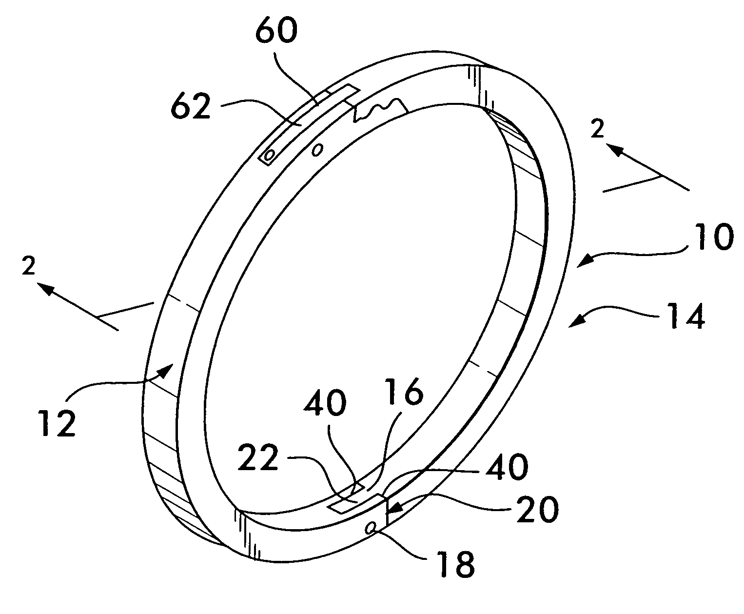
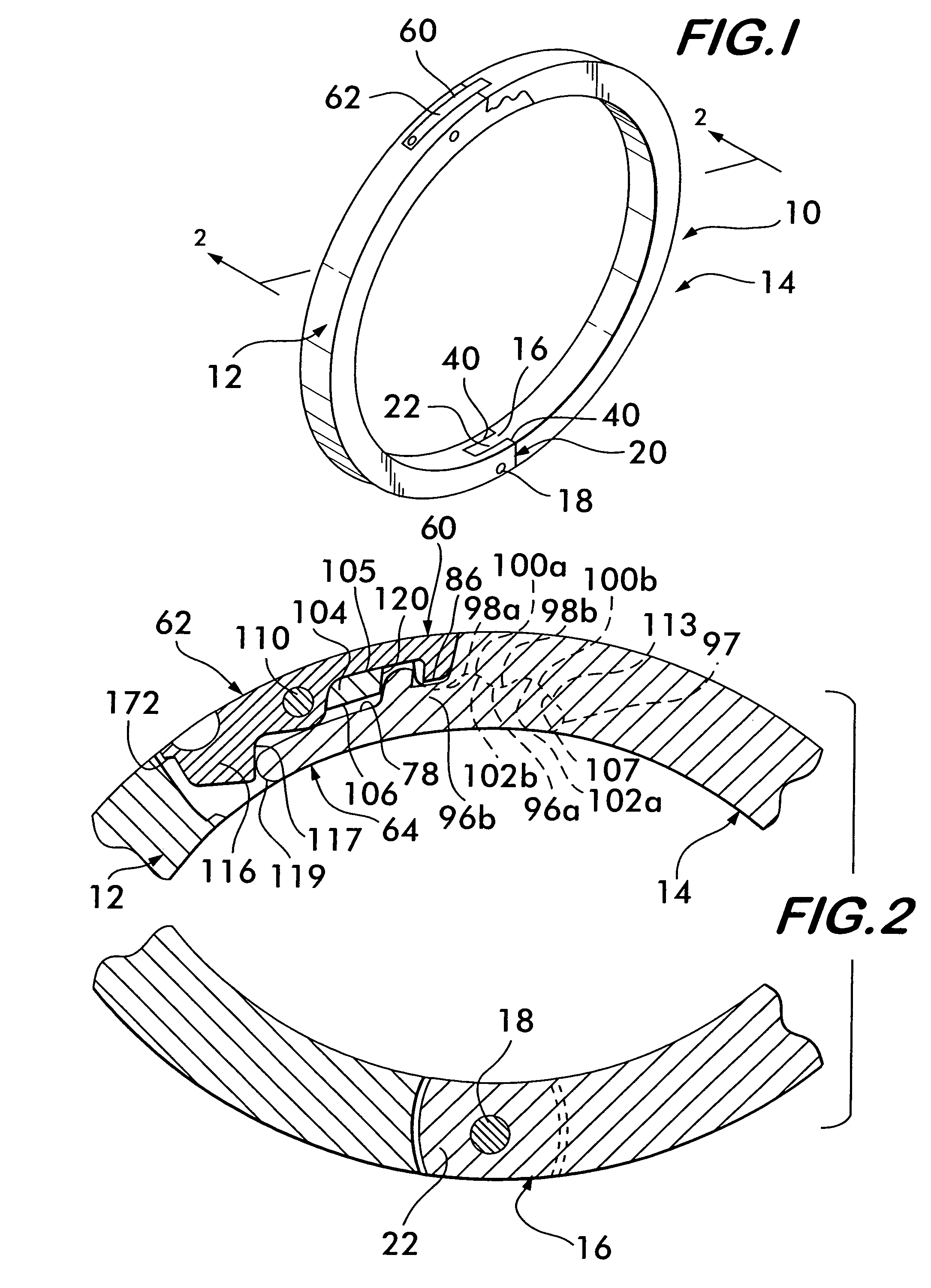
[0021]Referring now to the various figures wherein like reference characters refer to like parts, an openable ring with a latch mechanism is generally shown at 10 in FIG. 1. The device 10 basically comprises a pair of arcuate sections 12 and 14 pivotally interconnected through a hinge connection 16 adjacent one of their contiguous ends, and including a latch mechanism 60 adjacent their opposite contiguous ends.

[0022]Referring to FIGS. 1 and 2, the hinge connection 16 includes a hinge pin 18 extending through aligned openings in yolk 20 of section 12 and tang 22 of section 14. At this point it should be noted that the ring sections 12 and 14 are preferably made of a precious metal, e.g., gold, silver or platinum, and are formed from wax impressions of the ring sections in a conventional investment casting operation. Yoke 20 also includes leg sections 40. The details of the construction and operation of the hinge connection are set forth in detail in U.S. Pat. No. 5,136,858, which is ...


PUM


Abstract

An openable ring that is arranged to be worn about a portion of a body of a person. The ring includes first and second arcuate sections that are pivotally interconnected at one end of the ring for permitting pivotal movement of the arcuate sections between opened and closed positions. At the end opposite the pivotal interconnection, each arcuate section includes a pair of locking extensions, the locking extensions being transversely aligned with one another. Each locking extension has a locking surface which comprises a sum of more than two alternating hill and valley portions. The hill and valley portions of each respective locking surface cooperate with each other to releasably retain the arcuate sections in a closed position to define a closed ring having an inner surface and an outer surface. The inner surface defines an interior passage for receiving a portion of the person's body, e.g., a finger.

Description

BACKGROUND OF THE INVENTION[0001]1. Field of Invention[0002]This invention relates generally to ring-like objects designed to be worn as jewelry, and more particularly to rings which are enabled to be releasably opened for fitting about a portion of the wearer's body, e.g., finger, which are resistant to accidental opening, and which are easily opened when desired.[0003]2. Description of Related Art[0004]All references cited herein are incorporated herein by reference in their entirety.[0005]Conventional finger rings or other jewelry arranged to be worn about a portion of the body must have a sufficient diameter to slide over the knuckle or other bony protuberance adjacent the point at which the ring is to be worn. Normally, such action does not present any problem since the difference in diameter between the bony protuberance, e.g., knuckle, and the portion on which the ring is worn is sufficiently small so that a properly fitting ring is comfortable to wear, to put on and to remov...

Claims


Application Information

Patent Timeline
IPC IPC(8): A44C19/00A44C5/00A44C9/02
CPCA44C9/0046A44C5/2042
Inventor BRUNER, MATES A.
Owner HANNIG ARTHUR
Why Eureka
Try Eureka