Methods and apparatus for connecting tubulars while drilling

a technology of tubular connections and tubulars, which is applied in the direction of drilling/well accessories, sealing/packing, manufacturing tools, etc., can solve the problems of time-consuming re-starting of circulation throughout the wellbore, and increased mud weighting during intermittent cessation of fluid circulation

Inactive Publication Date: 2006-09-19
WEATHERFORD TECH HLDG LLC
View PDF169 Cites 103 Cited by
  • Summary
  • Abstract
  • Description
  • Claims
  • Application Information

AI Technical Summary

Benefits of technology

[0015]The present invention first provides an apparatus that permits sections of tubulars, such as drill pipe, liner and casing to be connected to or disconnected from a string of pipe during a drilling operation. The apparatus further permits the sections of drill pipe to be both rotated and axially translated during the connection or disconnection process. The apparatus further allows for the continuous circulation of fluid to and through the tubular string during the makeup or breakout process.

Problems solved by technology

Interruption of drilling may mean that the circulation of the mud stops and has to be re-started when drilling resumes.
Since the mud is a long fluid column, the resumption of circulation throughout the wellbore can be time consuming.
Such activity may also have deleterious effects on the walls of the wellbore being drilled, leading to formation damage and causing problems in maintaining an open wellbore.
Intermittent cessation of fluid circulation may require additional weighting of the mud.
The additional weighting of the mud to compensate for cessation of fluid circulation adds expense to the operation.
Further, the act of “breaking” the pumps to restart fluid circulation following a cessation of circulation may result in over pressuring of a downhole formation.
This can trigger formation damage or even a loss of fluids downhole, endangering the lives of the drilling crew due to loss of hydrostatic pressure.
Of course, the additional weighting of drilling mud adds expense to the drilling operation.
Therefore, valuable time loss occurs when drilling stops in order to connect the next successive section of drill pipe.
Additionally, starting rotation of the drill string can over torque portions of the drill string, causing failure from the additional stress.
However, inability to continue to advance the tubular string down the borehole during the connection process temporarily stops drilling into the formation.

Method used


Image

  • Methods and apparatus for connecting tubulars while drilling
  • Methods and apparatus for connecting tubulars while drilling
  • Methods and apparatus for connecting tubulars while drilling

Examples


Embodiment Construction

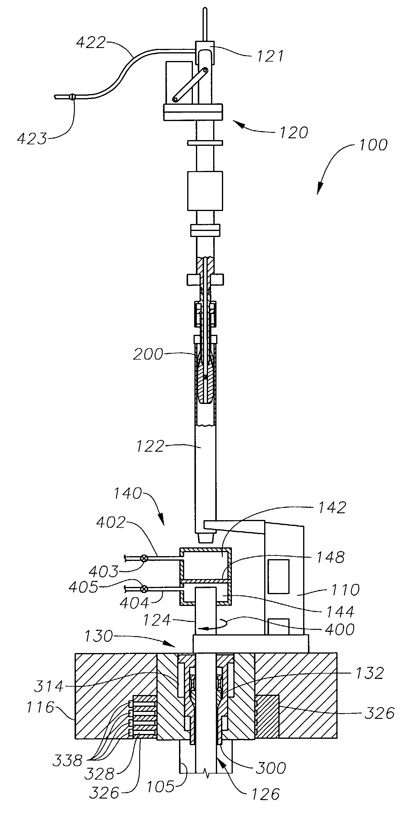
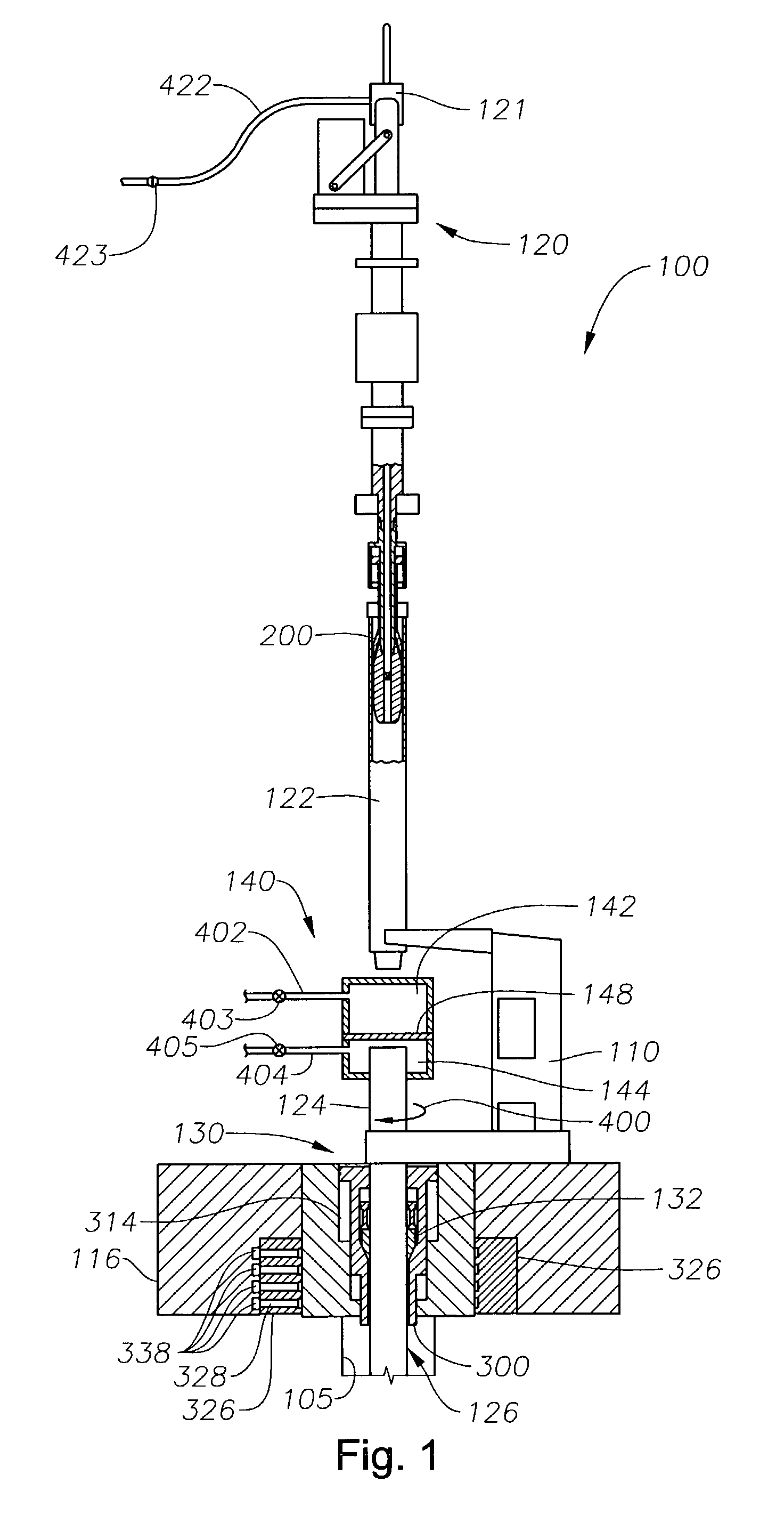
[0032]FIG. 1 presents a sectional view of an embodiment of a rig assembly 100 for continuously drilling. A wellbore 105 is being formed by operation of the rig assembly 100. As will be described, the novel rig assembly 100 provides three basic components: (1) a top drive mechanism 120, (2) a rotary drive mechanism 130, and (3) a fluid circulating device 140 disposed between the top drive mechanism 120 and the rotary drive mechanism 130. Each of these three components is seen in FIG. 1.

[0033]The rig assembly 100 of FIG. 1 is intended to primarily show the relative positions of the top drive mechanism 120, the rotary drive mechanism 130 and the fluid circulating device 140. It is understood that numerous other components of a typical drilling rig exist but are not shown. Examples of such components (not shown) include the V-door, the pipe rack, the elevators, the derrick structure and the dope bucket. However, several additional rig components are seen in the drawing of FIG. 1.

[0034]F...


PUM


Abstract

The present invention provides an apparatus that permits sections of tubulars to be connected to or disconnected from a string of pipe during a drilling operation. The apparatus further permits the sections of drill pipe to be rotated and to be axially translated during the connection or disconnection process. The apparatus further allows for the continuous circulation of fluid to and through the tubular string during the makeup or breakout process. The apparatus defines a rig assembly comprising a top drive mechanism, a rotary drive mechanism, and a fluid circulating device. Rotation and axial movement of the tubular string is alternately provided by the top drive and the rotary drive. Additionally, continuous fluid flow into the tubular string is provided through the circulation device and alternately through the tubular section once a connection is made between an upper tubular connected to the top drive mechanism and the tubular string.

Description

STATEMENT OF RELATED APPLICATIONS[0001]This application is a continuation-in-part of a U.S. patent application Ser. No. 10 / 011,049, and was filed Dec. 7, 2001 now U.S. Pat. No. 6,668,684 and is also incorporated by reference in its entirety. The parent application is entitled “Improved Tong for Wellbore Operations.”[0002]The parent patent application was filed as a division of U.S. Ser. No. 09 / 524,773. That application was filed on Mar. 14, 2000, and was entitled “Wellbore Circulation System.” That application has now issued as U.S. Pat. No. 6,412,554 to Allen, et al and is incorporated by reference in its entirety.BACKGROUND OF THE INVENTION[0003]1. Field of the Invention[0004]The present invention generally relates to methods and apparatus for the continuous drilling of a wellbore through an earth formation. More particularly, the present invention pertains to the continuous circulation of fluid through two tubulars that are being connected or disconnected during a wellbore drilli...

Claims


Application Information

Patent Timeline
Patent Type & Authority Patents(United States)
IPC IPC(8): B25B17/00E21B19/16E21B3/04E21B17/00E21B19/10E21B19/24E21B21/01E21B21/10E21B33/068
CPCE21B3/04E21B17/00E21B19/10E21B33/068E21B19/24E21B21/01E21B21/106E21B19/164E21B19/16E21B21/00
Inventor HAUGEN, DAVID M.HABETZ, JEFFREY MICHAEL
Owner WEATHERFORD TECH HLDG LLC
Why Eureka
Try Eureka