
Fluid dispenser device of the multi-dose type

a dispenser device and multi-dose technology, applied in the direction of liquid transfer devices, instruments, single-unit apparatuses, etc., can solve the problems of not being able to implement a standard assembly method, all existing lateral actuator systems do not solve problems, and the system suffers from numerous problems, etc., to achieve simple and inexpensive manufacturing and assembly, and excellent spray quality

Inactive Publication Date: 2006-09-19
APTAR FRANCE SAS
View PDF8 Cites 73 Cited by
  • Summary
  • Abstract
  • Description
  • Claims
  • Application Information

AI Technical Summary

Benefits of technology

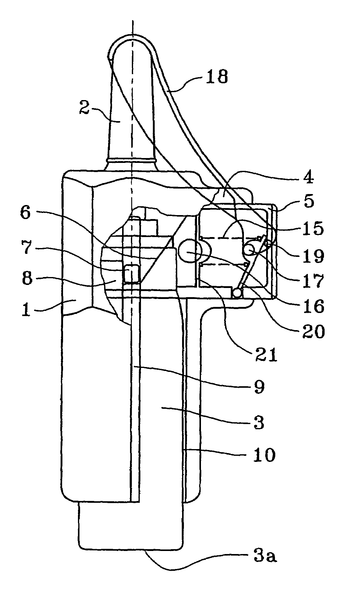
The present invention provides a fluid dispenser device that overcomes the drawbacks of existing devices. The device is simple and inexpensive to manufacture and assemble. It guarantees excellent spray quality and delivers a full dose of fluid each time it is actuated, regardless of the resistance of the pump or the quantity of fluid. The device can be actuated by a lateral actuating system or a standard actuating system. The device is fixed inside the remainder of the device without any modification by the presence of the lateral actuating system. The actuating element moves in a different direction than the piston or valve member of the dispensing member, and the actuating element has a cam surface that co-operates with the reservoir or a fixing ring to move the reservoir axially relative to the piston or valve member of the dispensing member to dispense a dose of fluid. The device is easy to assemble and can be fixed inside the device by snap-fastening. The end-wall of the reservoir remains accessible for being actuated by hand by pushing axially on the end-wall of the reservoir. The invention provides a fluid dispenser device that overcomes the drawbacks of existing devices and is more efficient and cost-effective.

Problems solved by technology

Such systems suffer from numerous problems.
In particular, they do not make it possible for a standard assembly method to be implemented by the manufacturer of the fluid to be dispensed, which is generally a pharmaceutical, because it is then not possible merely to insert the unit formed by the reservoir and by the pump into the dispensing head, as is usual in devices that are actuated by hand.
In addition, such systems make lateral actuation essential, even though the user might, for various reasons, such as dexterity problems, a habit difficult to change, etc. sometimes prefer to actuate the device in the conventional manner, i.e. by pressing by hand on the end-wall of the reservoir.
In addition, all of the existing lateral actuating systems do not solve the problem which is typical with most spray pumps and which relates to the dose-metering accuracy and the spray quality being dependent on the speed and the force with which the user actuates the device.
Thus, partial actuation can result in a partial dose being dispensed or in the spray quality being degraded.

Method used


Image

  • Fluid dispenser device of the multi-dose type
  • Fluid dispenser device of the multi-dose type
  • Fluid dispenser device of the multi-dose type

Examples


first embodiment

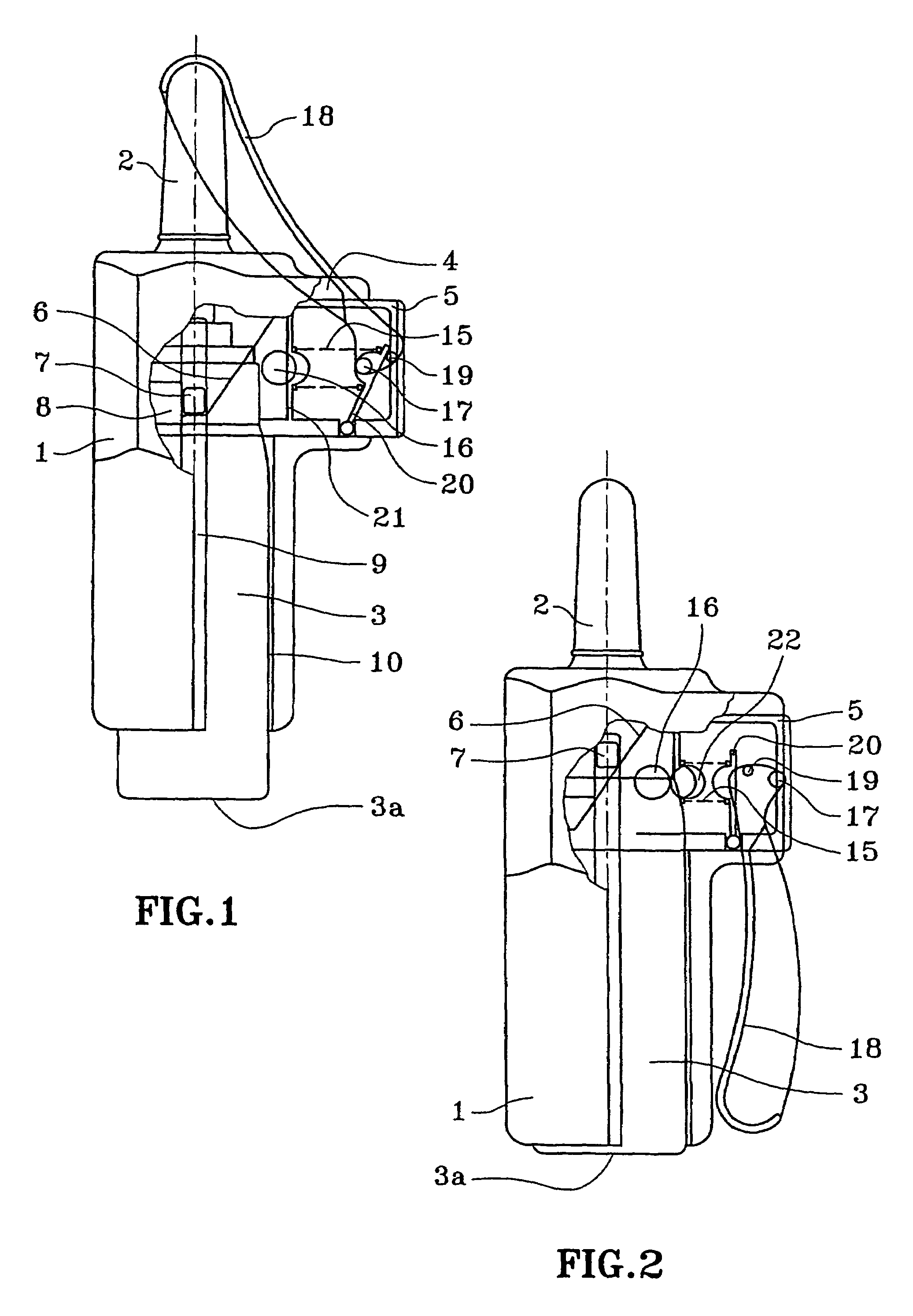
[0029]In a first embodiment shown in FIGS. 1 and 2, the force-regulating means comprise resilient means such as a spring 15 which co-operates with the actuating element 5 to urge it towards its actuating position when the spring is compressed. The force-regulating means further include trigger means 16 that are preferably implemented in the form of one or more side buttons. The buttons 16 retain the actuating element in the rest position (shown in FIG. 5) against the force exerted by the spring 15, until the user presses on the buttons 16 to release the locking of the actuating element 5, thereby enabling it to move into its actuating position under the effect of the resilient force of the spring 15, and thus to move the reservoir 3 relative to the piston of the pump to deliver a dose. It is thus the characteristics of the spring 15 that determine the force exerted by the actuating element on the pump, and therefore the actuating force on the pump is independent of the force exerted...

second embodiment

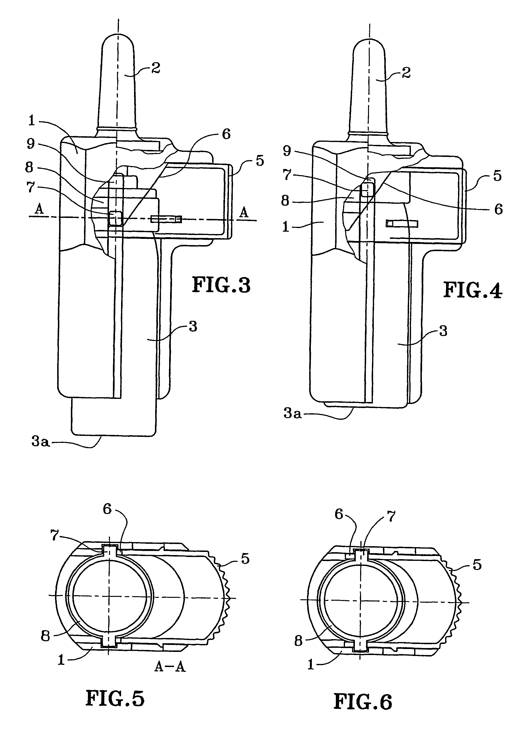
[0032]In FIGS. 3 to 6, a second embodiment is shown that differs from the embodiment shown in FIGS. 1 and 2 in that the device does not have the pre-compressible resilient means for exerting a force on the actuating element 5 during actuation of the device. In the example shown in FIGS. 3 to 6, the force exerted by the user on the lateral actuating element 5 is directly transformed into a force for axially moving the piston of the pump by the slope 6 forming the cam surface and co-operating with the peg 7 integral with the fixing ring 8. In this embodiment, the force-regulating means may be implemented in the form of a varying gradient of said sloping surface 6. During the actuating stroke, pumps generally change their resistance, and therefore the force required for actuation. Such increases in resistance during the stroke take place sometimes constantly, and sometimes very quickly. An appropriate variation in the inclination of the cam surface 6 can fully compensate for such incre...


PUM


Abstract

A fluid dispenser device a body (1), a fluid reservoir (3), a dispensing member, such as a pump or a metering valve having a piston or a valve member that is mounted to move axially, which dispensing member is fitted to the reservoir (3), and an actuating element (5) mounted to move between a rest position and an actuating position, for actuating the dispensing member and thus for selectively dispensing the fluid contained in the reservoir (3), fluid dispenser device being characterized in that the direction in which actuating element (5) moves is different from, and in particular perpendicular to, the axial direction in which the piston or the valve member of the dispensing member moves, the actuating element (5) having an end portion provided with the cam surface (6) which co-operates with the reservoir (3) or a fixing ring (8) adapted to fix the dispensing member to the reservoir (3) so that the actuating member (5) being moved substantially radially into its actuating position causes the reservoir (3) to be moved axially relative to the piston or to the valve member of the dispensing member so as to dispense a dose of fluid.

Description

CROSS-REFERENCE TO RELATED APPLICATIONS[0001]This is a divisional of application Ser. No. 10 / 362,477, filed Feb. 24, 2003 now U.S. Pat. No. 6,860,411, which is a National Stage Application filed under §371 of PCT Application No. PCT / FR01 / 02684, filed Aug. 28, 2001; the above noted prior applications are all hereby incorporated by reference.FIELD OF THE INVENTION[0002]The present invention relates to a fluid dispenser device, and more particularly to a fluid spray device of the multi-dose type having a lateral actuating system.BACKGROUND[0003]In the field of multi-dose spray devices, several systems for laterally actuating the pump of the device have been developed recently.[0004]Such a system is generally constituted by a body containing the entire spray device and provided with a pivotally mounted lever system acting against the end-wall of the fluid reservoir and pushing it axially, during actuation, towards the dispensing head so as reproduce the movement of the hand during stand...

Claims


Application Information

Patent Timeline
Patent Type & Authority Patents(United States)
IPC IPC(8): B65D83/20B67D5/42B05B11/00A61M15/00B67D7/60B67D7/84
CPCA61M15/0065B05B11/00B05B11/3091B05B11/3052B05B11/3056B05B11/0037B05B11/0038B05B11/0032B05B11/1091B05B11/1056B05B11/1052
Inventor STRADELLA, GUISEPPE
Owner APTAR FRANCE SAS
Learn More