Film reel

a film reel and reel body technology, applied in the direction of data recording, instruments, record carrier driving mechanisms, etc., can solve the problems of destroying the vast majority of motion picture production copies, required, and a large number of motion picture film produced

Inactive Publication Date: 2006-09-19
CIRCULAR MOTION PRODS
View PDF5 Cites 7 Cited by
  • Summary
  • Abstract
  • Description
  • Claims
  • Application Information

AI Technical Summary

Benefits of technology

[0017]The present intervention involves a motion picture reel having detachable components but constructed in such a manner as to prohibit any significant relative angular movement between the laterally confining side retainers. This is achieved by constructing each laterally confining retainer wit

Problems solved by technology

In the motion picture industry, motion pictures are timed for release at a great number of locations during and immediately following very expensive promotional advertising campaigns.
Following the promotional period, however, the multitude of copies of the motion picture film produced and previously required are no longer necessary, and indeed, constitute a problem.
While certainly a limited number of copies of the film are preserved for possible recirculation and for use as masters for the possible reproduction of additional copies at a future time, the great majority of the copies of motion pictures produced are destroyed following a limited period of wide-spread exhibition in movie theaters.
The expense of storing the very large number of copies which were once necessary in order to exhibit the motion picture at a multitude of different movie theaters cannot be justified.
The cost of protection and storage of each copy of the motion picture film far outweighs the incremental cost of producing another motion picture copy should another copy be required.
However, this was a very time consuming, and therefore expensive process.
As a result, smashing of the reel was laborious and also at times difficult.
Moreover, the cost of replacing these

Method used


Image

  • Film reel
  • Film reel
  • Film reel

Examples


Embodiment Construction

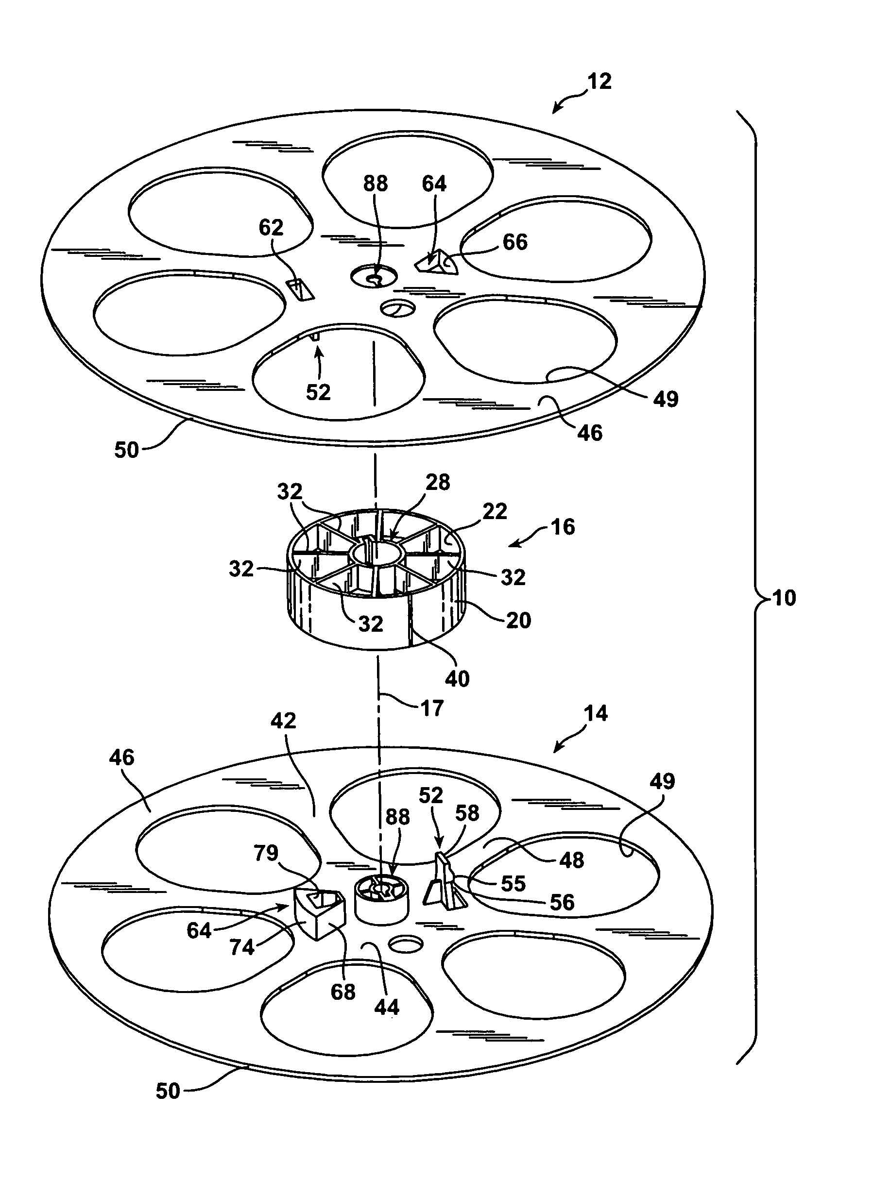
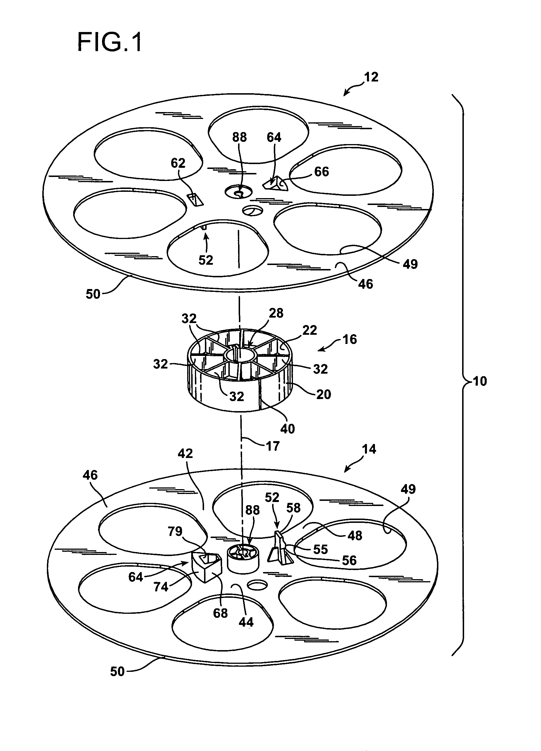
[0042]FIG. 1 illustrates a motion picture film reel 10 constructed according to the present invention. The motion picture film reel 10 is comprised of a pair of structurally identical, laterally confining retaining members 12 and 14 and a hollow, generally disc-shaped hub 16 located therebetween. All of the components members 12, 14, and 16 of the motion picture film reel 10 are formed of acronitrile-butadiene-styrene (ABS).

[0043]The centrally located hub 16 of the type utilized in the motion picture industry has a very standardized construction. The hub 16 is illustrated in isolation in FIG. 8. The hub 16 has an outer, cylindrical, annular rim 18 having an outer surface 20 that is 10 cm in diameter and an inner surface 22. The encircling rim 18 has opposing edges 24 and 26 and the hub 16 is 3.4 cm in thickness as measured between the opposing, circular edges 24 and 26.

[0044]At its center the hub 16 is provided with a substantially cylindrical, annular core 28 having an internal dia...


PUM


Abstract

A motion picture reel is provided with releaseably engageable and disengageable components including a pair of identical, laterally confining retaining members and a hub located therebetween. The retaining members and the hub are all separable from each other. Each retaining member has a prong with a catch on it and a latching member with a latch defined on it located diametrically opposite the prong. The latching members each have radially outwardly diverging side walls. The latching members fit snugly into truncated sector-shaped cavities formed between radial spoke partitions between the central core and the rim of the hub. Stiffening webs extended transversely across the hub between some of the spoke partitions and have apertures in them that allow passage of the prongs through the stiffening webs and into engagement with the latching lips of the latching projections beyond. The tips of the prongs are accessible for release through the open bases of the latching members.

Description

BACKGROUND OF THE INVENTION[0001]1. Field of the Invention[0002]The present invention relates to motion picture reels upon which motion picture film is wound and unwound as it is passed through a motion picture projector for presentation of a motion picture to a viewing audience.[0003]2. Description of the Prior Art[0004]Motion pictures are created by a series of photographs taken rapidly in sequence and arranged on a length of film. The film is wound on a motion picture reel and fed through a motion picture projector at a predetermined speed that is rapid enough to produce the illusion of actual movement of the figures in the sequence of photographs as the photographs are projected on the screen. The film is wound on the motion picture reel in a helical fashion about a hub that is fixed between a pair of much larger, narrow, planar retaining members. As film is advanced through the projector it is pulled off of one reel, advanced through the projector, and wound on a take-up reel. ...

Claims


Application Information

Patent Timeline
IPC IPC(8): B65H75/14
CPCB65H75/22G11B23/044G11B15/32B65H2701/5136B65H75/2245B65H75/2281
Inventor SCHAEFER, ROBERT J.
Owner CIRCULAR MOTION PRODS
Why Eureka
Try Eureka