Adjustment mechanism for a variable-shape wing

a variable-shape, wing technology, applied in the direction of wing adjustment, aircraft components, without power amplication, etc., can solve the problems of complex actuator system, unfavorable weight design, unreliability, etc., and achieve high redundancy, increase equipment-related expenditure, and high security against breakdown

Inactive Publication Date: 2006-09-19
EADS DEUT GMBH
View PDF17 Cites 18 Cited by
  • Summary
  • Abstract
  • Description
  • Claims
  • Application Information

AI Technical Summary

Benefits of technology

[0016]Through the concept according to the invention of a line of whirl chambers driven by drive tube sections, a high redundancy can be achieved in the drive chain for the respective adjustment area and thus a high security against breakdowns can be achieved, since the components used can be installed in a parallel manner without any substantial increase in equipment-related expenditure.
[0017]The solution according to the invention results in an adjustment area, the adjustment conditions of which produce a relatively favorable resistance and improved aerodynamic effectiveness. Moreover, a reduction in noise can be achieved.
[0018]To realize the adjustment mechanism according to the invention, relatively parts are necessary so that a great reliability can be achieved. Moreover, a relatively small space is required. The relatively low number of components and the favorable load introduction and load distribution result in a relatively low weight for the adjustment mechanism.

Problems solved by technology

Adjustment mechanisms for adjusting the curvature of a wing are known from U.S. Pat. No. 4,349,169, DE 680 525 and EP 860 355; however, their actuator system is complex and therefore unreliable and unfavorably designed with respect to weight.
A further disadvantage of the prior art is that hydraulic cylinders are used that are supported on the primary structure in a jointed manner.
Another disadvantage resulting from this approach is that the loads are introduced only on locally very limited points in the structure.
A relatively great material accumulation is thus necessary, which in turn leads to an increase in weight.
In turn greater loads can consequently result on the flap, and longitudinal stability problems can occur, in particular with stabilized aircraft.

Method used


Image

  • Adjustment mechanism for a variable-shape wing
  • Adjustment mechanism for a variable-shape wing
  • Adjustment mechanism for a variable-shape wing

Examples


Embodiment Construction

[0073]The particulars shown herein are by way of example and for purposes of illustrative discussion of the embodiments of the present invention only and are presented in the cause of providing what is believed to be the most useful and readily understood description of the principles and conceptual aspects of the present invention. In this regard, no attempt is made to show structural details of the present invention in more detail than is necessary for the fundamental understanding of the present invention, the description taken with the drawings making apparent to those skilled in the art how the several forms of the present invention may be embodied in practice.

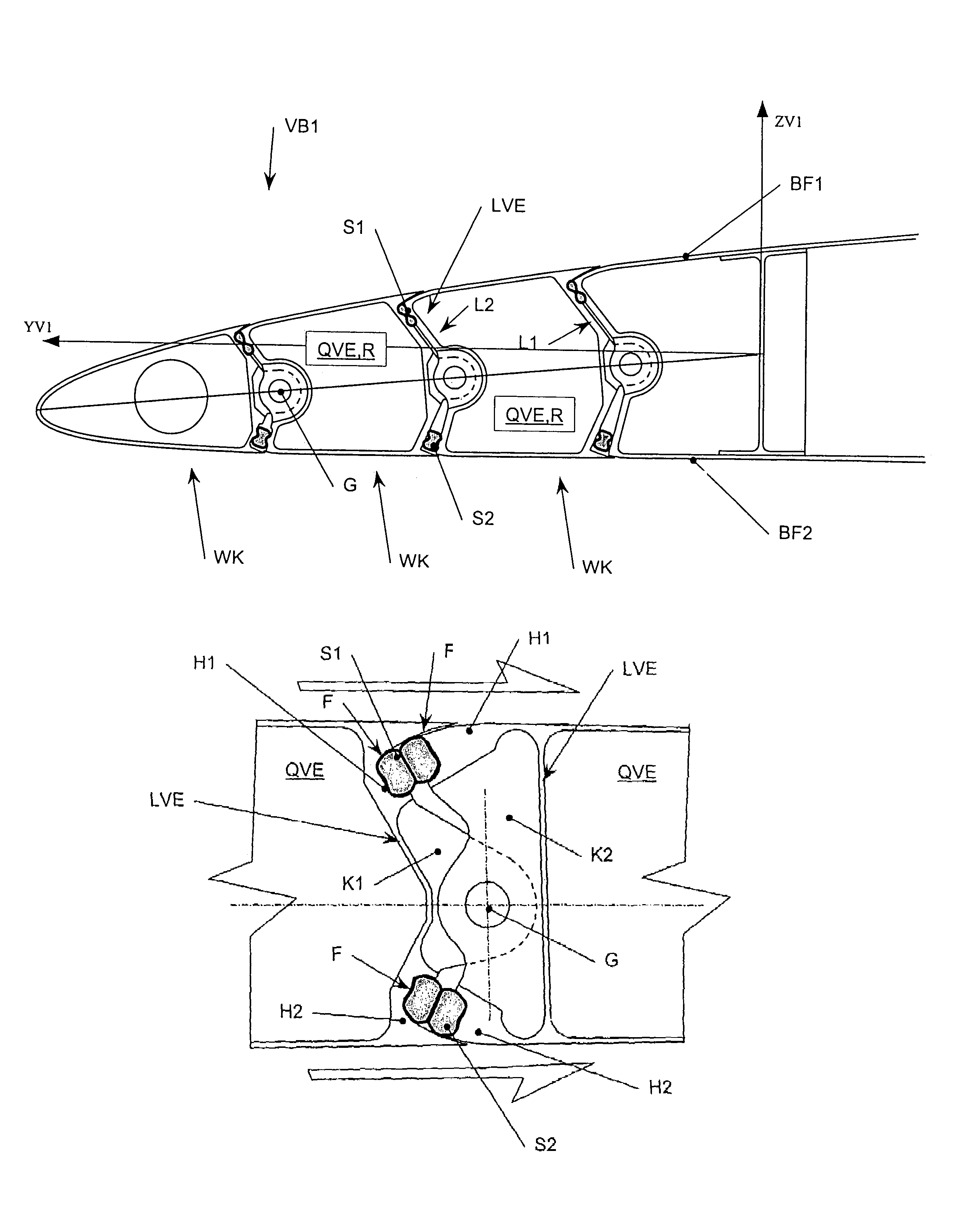
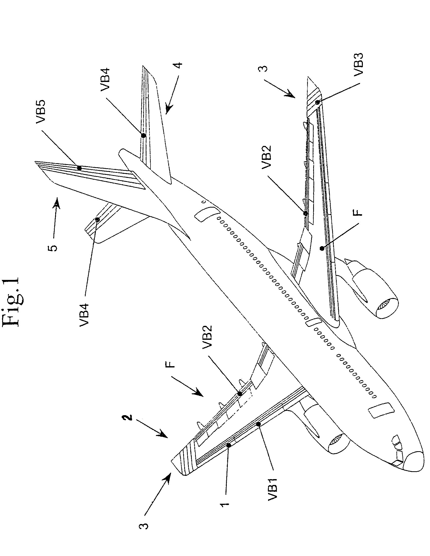
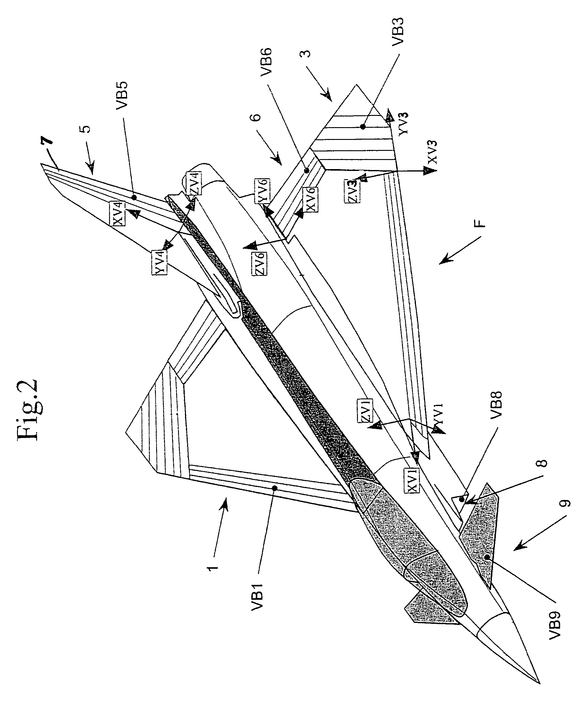
[0074]According to the invention, an adjustment mechanism is provided for a variable-shape wing area that in general is a part of a flow surface or forms this essentially or completely. The flow surface can be used in particular for an aircraft and can be, e.g., a wing, an empennage or a front face or canard.

[0075]Example...


PUM


Abstract

Adjustment mechanism for adjustment area of variable-shape flow surface with two opposite skin surfaces includes plurality of whirl chambers swivelably arranged next to one another so that the whirl chambers are swivelable relative to one another, and the whirl chambers include lateral stiffening elements and longitudinal stiffening elements. Joints are structured and arranged to jointedly couple lateral stiffening elements and longitudinal stiffening elements of the whirl chambers, and a first drive tube section and a second drive tube section are arranged between adjacent longitudinal stiffening elements. A pump is coupled to first and second drive tube sections and control device is functionally connected to pump to swivel adjacent whirl chambers around joint axes via complementary volume changes in first and second drive tube sections. The instant abstract is neither intended to define the invention disclosed in this specification nor intended to limit the scope of the invention in any way.

Description

CROSS-REFERENCE TO RELATED APPLICATIONS[0001]The present application claims priority under 35 U.S.C. §119 of German Patent Application No. 103 17 258.0, filed on Apr. 14, 2003, the disclosure of which is expressly incorporated by reference herein in its entirety.BACKGROUND OF THE INVENTION[0002]1. Field of the Invention[0003]The invention relates to an adjustment mechanism for a variable-shape wing.[0004]The wing can be in general a part of a flow surface or can form it essentially or completely. The flow surface can be used in particular for an aircraft and can be, e.g., a wing, an empennage or a front face or a canard.[0005]2. Discussion of Background Information[0006]Adjustment mechanisms for adjusting the curvature of a wing are known from U.S. Pat. No. 4,349,169, DE 680 525 and EP 860 355; however, their actuator system is complex and therefore unreliable and unfavorably designed with respect to weight. A further disadvantage of the prior art is that hydraulic cylinders are use...

Claims


Application Information

Patent Timeline
Patent Type & Authority Patents(United States)
IPC IPC(8): B64C13/36B64C3/48B64C9/02
CPCB64C9/02B64C3/48B64C3/38B64C5/10B64C9/00
Inventor PEREZ-SANCHEZ, JUAN
Owner EADS DEUT GMBH
Why Eureka
Try Eureka