Omni-directional wind turbine electric generation system

a wind turbine and electric generation technology, applied in the direction of electric generator control, renewable energy generation, greenhouse gas reduction, etc., can solve the problems of unbalanced structure, large noise, and inability to achieve the potential benefits of the system

Inactive Publication Date: 2006-09-19
WEPOWER +1
View PDF15 Cites 62 Cited by
  • Summary
  • Abstract
  • Description
  • Claims
  • Application Information

AI Technical Summary

Problems solved by technology

Among its many disadvantages are the need to keep it pointed into the wind, to provide for gearing, braking, and feathering controls to transfer the torque to an off-axis generator, and to keep the rotational speeds within acceptable limits.
The major problem with vertical axis rotors is that the wind blows on both sides of the axis of rotation, so that something must be done on a net basis to the baffles or airfoils on one side to resist the wind, and on the other side to pass the wind.
This requires mechanism for the purpose, and generates considerable noise.
Also the structure is not balanced, because it supports a much larger lateral load on one side than on the other.
The potentials of this wind turbine were neither appreciated, nor were the problems solved, so its potential benefits have remained unaccomplished.
While this appears to be a commonplace thing, these gear boxes are expensive, noisy, need maintenance, have speed limitations, and constitute a slow-speed drag which raises the lowest wind speed to which the system can respond and thereby forfeits the energy content of slow wind speed.
An overspeed can lead to swift destruction of the mechanical system.
This seriously reduces the range of wind speeds from which energy can be extracted, and forfeits much energy that should be obtainable from high wind speeds.
Yet another disadvantage of known tower-supported systems is their tendency to be toppled by high velocity winds.

Method used


Image

  • Omni-directional wind turbine electric generation system
  • Omni-directional wind turbine electric generation system
  • Omni-directional wind turbine electric generation system

Examples


Embodiment Construction

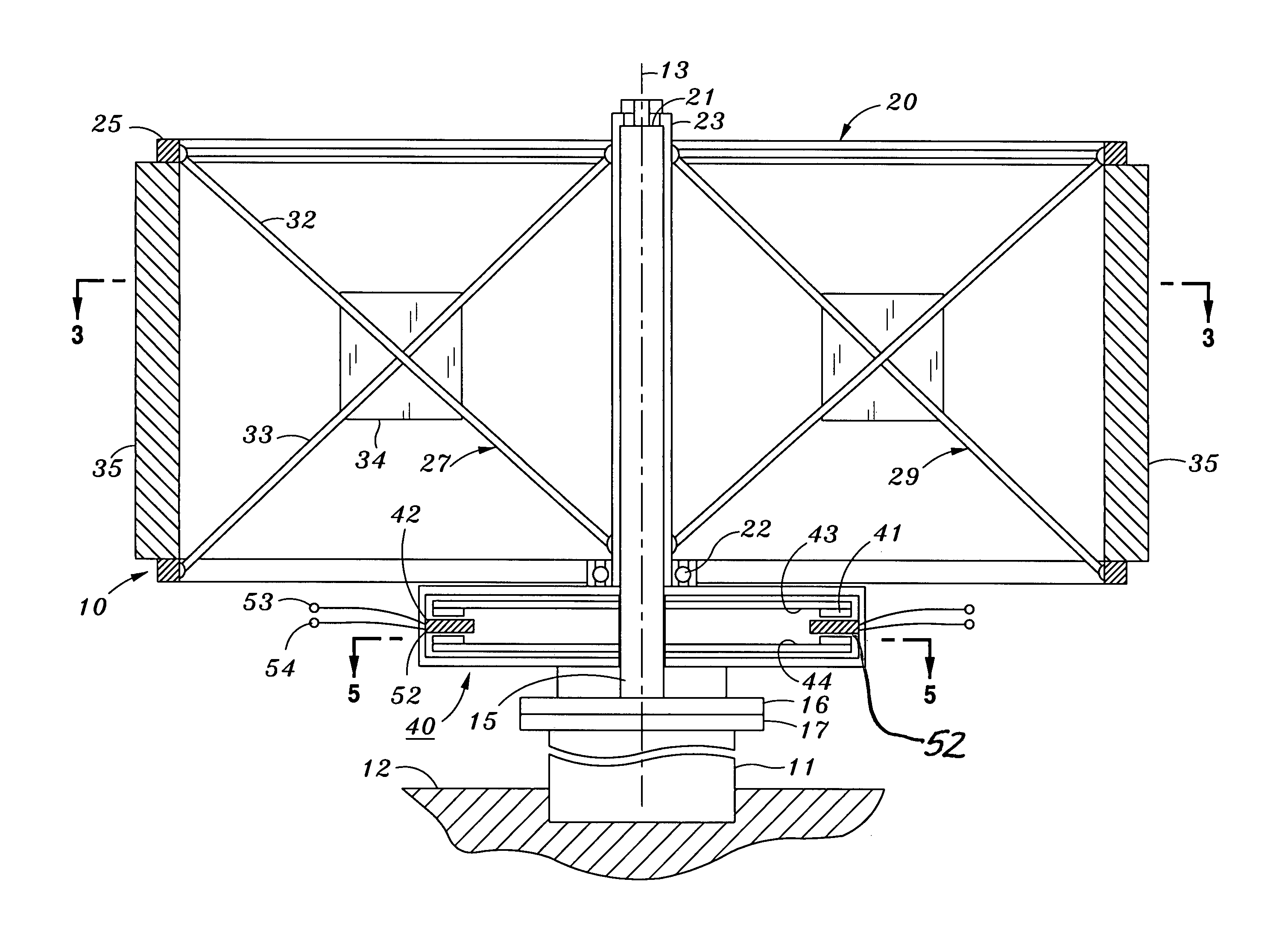
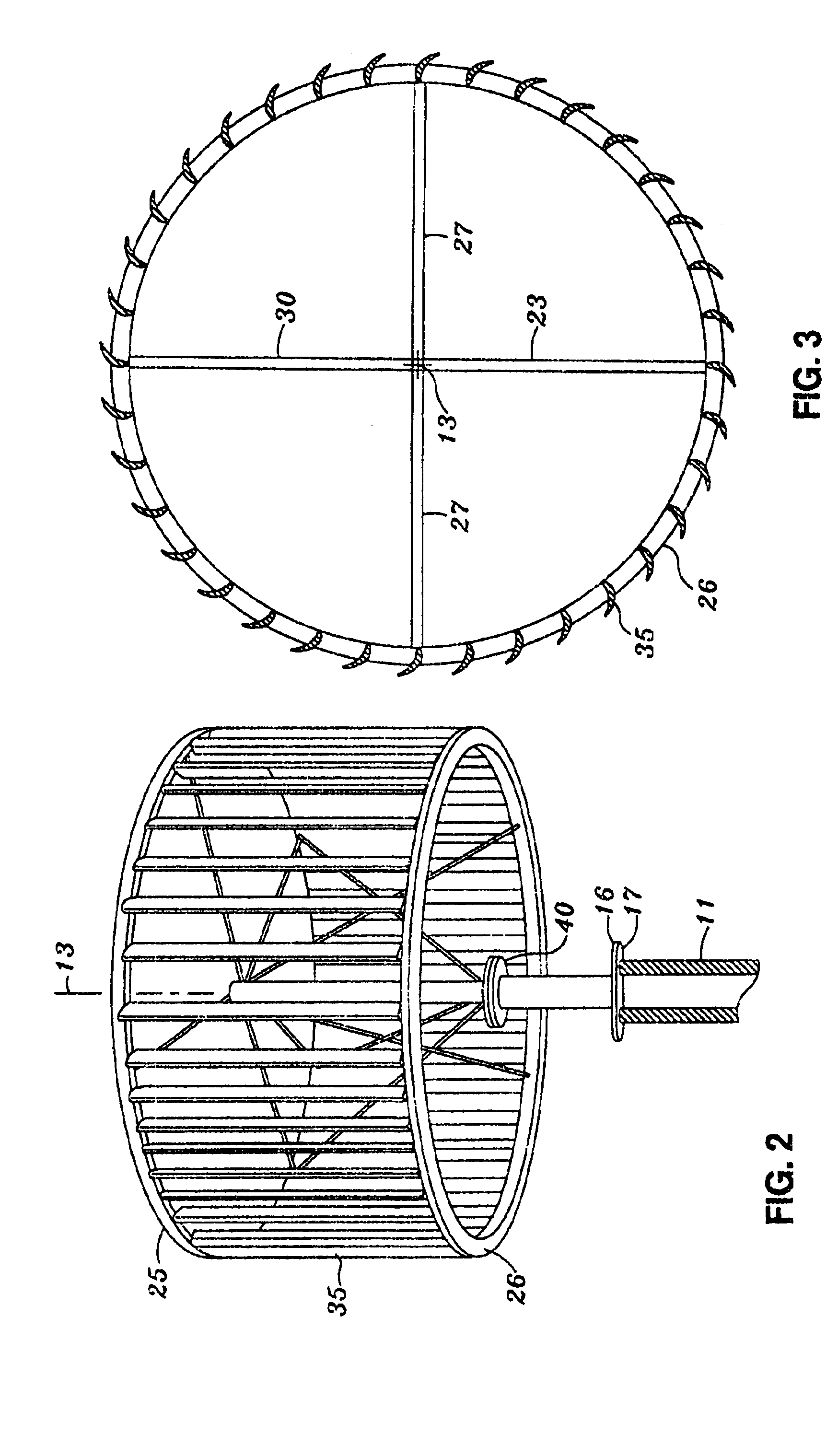
[0023]The system 10 of this invention is mounted to fixed structure 11 such as a heavy-walled tube set in a foundation 12. The system has a central axis 13 which is nominally upright. It may be inclined for best advantage, but this will be a rare occurrence.

[0024]A spindle 15 is fixed to structure 11, such as by bolted or welded flanges 16, 17. It does not rotate. A wind turbine rotor 20 is rotatably mounted to the spindle by bearings 21, 22. The wind turbine rotor includes a rotary tubular shaft 23 that is supported in compression by the bearings.

[0025]An upper ring 25 and a lower ring 26 are supported on shaft tube 25 by sets of spokes 27, 28, 29, 30 shown as four in number, although they may be more or fewer as required. The rings and spokes are rigid structures.

[0026]Spoke 27 is shown in detail as an example. It comprises a pair of diagonal rods 32, 33 extending from one or the other of the rings to the rotary shaft. Gusset plate 34 rigidly joins them at their intersection so th...


PUM


Abstract

An omni-directional wind turbine electric generation system including a wind rotor carrying wind responsive vanes which on one surface exert an aerodynamic lifting force and on the other a blocking force both of which exert a torque in the same rotational sense, and an electric generator directly connected to said wind rotor and coaxial therewith, without transmission means between them.

Description

FIELD OF THE INVENTION[0001]An electrical generation system driven by an omni-directional wind turbine, the system including a generator concentric with the wind turbine.BACKGROUND OF THE INVENTION[0002]Generation of electricity derived from structural response to the wind stream is a well-written story. The most familiar example is the windmill—a wind-driven propeller pointed into the wind by a trailing vane. This is the best-known representative of a class of rotary airfoils rotating around a horizontal axis. Among its many disadvantages are the need to keep it pointed into the wind, to provide for gearing, braking, and feathering controls to transfer the torque to an off-axis generator, and to keep the rotational speeds within acceptable limits.[0003]Attempts have been made to provide for omni-directional response to the wind, that is, the ability to be driven without directional adjustment no matter what the direction of the wind is. With such a device, it is unnecessary to-poin...

Claims


Application Information

Patent Timeline
Patent Type & Authority Patents(United States)
IPC IPC(8): F03D3/00F03D9/00H02P9/04
CPCF03D3/005F05B2220/7066Y02E10/74F05B2240/217F05B2220/7068
Inventor WATKINS, PHILIP G.
Owner WEPOWER
Why Eureka
Try Eureka