Vibration-type driving device, control apparatus for controlling the driving of the vibration-type driving device, and electronic equipment having the vibration-type driving device and the control apparatus

a technology of driving device and control apparatus, which is applied in the direction of piezoelectric/electrostrictive/magnetostrictive device, piezoelectric/electrostrictive/magnetostrictive device, piezoelectric/electrostrictive/magnetostriction machine, etc., can solve the problem of describing conventional vibration-type driving device, difficult to reduce the size of plate-like vibration element, and individual driving device driving performance fluctuation, etc. problem

Active Publication Date: 2006-09-19
CANON KK
View PDF3 Cites 55 Cited by
  • Summary
  • Abstract
  • Description
  • Claims
  • Application Information

AI Technical Summary

Benefits of technology

[0063]The protruding portions 3-1 and 3-2 are formed integrally with the driving plate 2 by means of press working or the like. Here, the protruding portions 3-1 and 3-2 and the driving plate 2 may be formed separately and then fixed to each other, but the integral formation thereof can produce such advantageous effects that it is possible to reduce the number of required parts and cost, it is possible to increase the assembly productivity of devices because of a reduction in the number of steps of assembly work, and it is possible to prevent precision fluctuations in individual parts because of positioning of parts being unnecessary.
[0064]FIG. 1B illustrates the structural arrangement for supporting the vibration element 1. As shown in FIG. 1B, a multi-layer piezoelectric element 5 is fixed to a printed circuit board 7, which supplies a driving signal (a driving voltage) to the multi-layer piezoelectric element 5. Also shown is a stationary member 8 fixed to an apparatus so as to mount the ultrasonic actuator 10 thereon. A support member 9 mounts the vibration element 1 on the stationary member 8 to allow vibration of the vibration element 1 and is arranged to bring the vibration element 1 into pressure contact with the slider 6. Although not shown, other structural members can be employed for supporting the vibration element 1, which may include fixing means for fixing the vibration element 1 in such a manner as not to hider the vibration thereof, means for bringing the vibration element and the driven element into pressure contact with each other, and means for supplying a driving signal to the piezoelectric element. Hereinafter, for the purpose of simplification, the printed circuit board 7, the stationary member 8 and the support member 9 will be omitted from the description of the structural arrangement of the vibration element 1. Note that an exemplary size of the vibration element 1 including the protruding portions 3-1 and 3-2 is 10×6×2 (mm).
[0065]FIGS. 2A and 2B show the shapes of the vibration element 1 occurring in two vibration modes (MODE-A and MODE-B). Each vibration mode is a flexural vibration mode in which the plate-like vibration element 1 is flexed in an out-of-plane direction. These two modes (MODE-A and MODE-B) will be described with reference to the X, Y and Z coordinate system.
[0066]The shape of the vibration element 1 is determined in advance so as to make the resonance frequencies in the two vibration modes approximately coincide with each other. The resonance frequency of the vibration element 1 shown in FIGS. 2A and 2B is about 80 kHz. FIG. 2A is a view of the vibration element 1 as seen from the Y direction. When the vibration element 1 is excited in MODE-A, nodes (α) of vibration appear at three points or lines (secondary flexural vibration mode) as shown in the lower half of FIG. 2A. These nodes extend in the Y direction of the vibration element 1.
[0067]In MODE-A, when the vibration element 1 is seen from the X direction, no nodes of vibration appear. The protruding portions 3-1 and 3-2 are disposed at or in the vicinity of positions where nodes occur in the vibration in MODE-A, as shown in FIG. 2A. Accordingly, the vibration in MODE-A causes the contact portions 4-1 and 4-2 to make a reciprocating motion in the X direction as indicated by arrows in FIG. 2A.
[0068]Thus, since the protruding portions 3-1 and 3-2 are disposed at or in the vicinity of positions of nodes in MODE-A, the protruding portions 3-1 and 3-2 can be displaced to the greatest extent in the X direction.

Problems solved by technology

However, there are disadvantages associated with the above-described conventional vibration-type driving devices.
In the first type (U.S. Pat. No. 5,698,930), which excites flexural vibration and longitudinal vibration, vibrations are excited at the plate-like elastic body in a longitudinal-vibration primary mode, so that it is difficult to reduce the size of the plate-like vibration element because an increased resonance frequency can result.
This can cause driving performance to fluctuate in individual driving devices.
However, in the first vibration mode of FIG. 35B, cross-like nodes occur in this flexural vibration mode, so that the distribution of strains becomes complicated.
Therefore, it is difficult to provide sufficient amount of vibratory displacement to the protruding portions 102a to 102d, and to exert a larger driving force on the driven element.

Method used


Image

  • Vibration-type driving device, control apparatus for controlling the driving of the vibration-type driving device, and electronic equipment having the vibration-type driving device and the control apparatus
  • Vibration-type driving device, control apparatus for controlling the driving of the vibration-type driving device, and electronic equipment having the vibration-type driving device and the control apparatus
  • Vibration-type driving device, control apparatus for controlling the driving of the vibration-type driving device, and electronic equipment having the vibration-type driving device and the control apparatus

Examples


first embodiment

(First Embodiment)

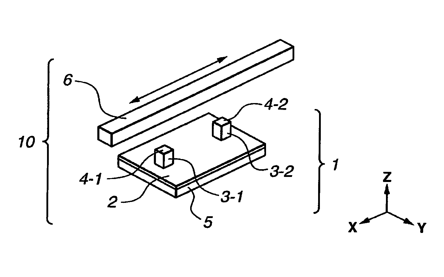
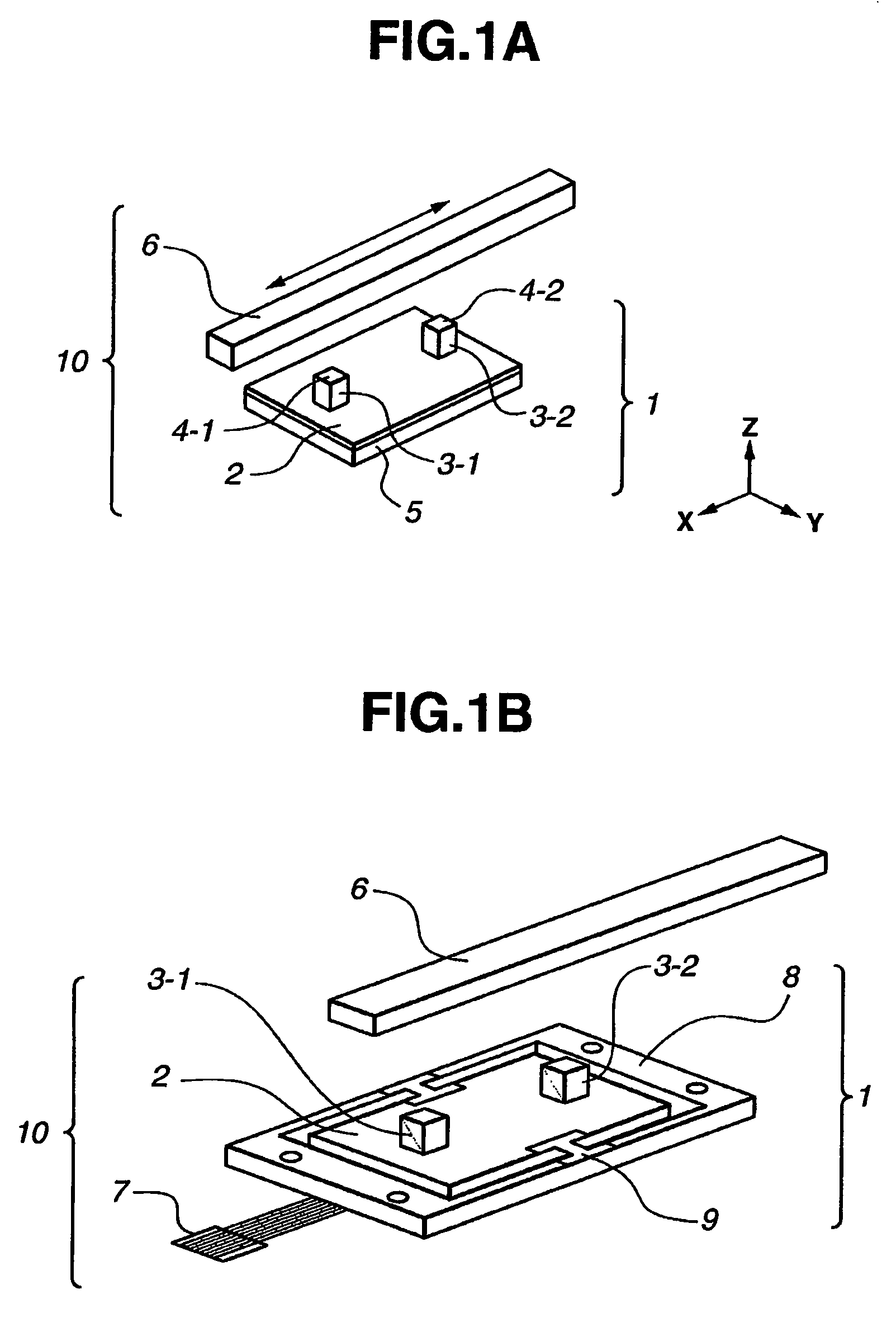
[0057]FIGS. 1A and 1B are perspective views showing the appearance of a linear-type ultrasonic actuator 10 serving as a vibration-type driving device according to a first embodiment of the invention.

[0058]In FIG. 1A, the linear-type ultrasonic actuator 10 is composed of a vibration element 1 and a linear slider 6.

[0059]The vibration element 1 is composed of a multi-layer piezoelectric element 5 formed into a rectangular thin-plate shape, and a driving plate 2 made of an elastic body and bonded integrally to one end surface of the multi-layer piezoelectric element 5. The multi-layer piezoelectric element 5 also has a plurality of thin-plate-like piezoelectric element films each having electrodes on the front surface thereof. The multi-layer piezoelectric element 5 is an electro-mechanical energy conversion element in which mechanical displacement occurs in response to an electrical signal being supplied thereto. Preferably, the size of the multi-layer piezoelectric ...

second embodiment

(Second Embodiment)

[0105]FIG. 8 is a perspective view showing the appearance of a linear-type ultrasonic actuator 10 serving as a vibration-type driving device according to a second embodiment of the invention.

[0106]In FIG. 8, the vibration element 1 is composed of a multi-layer piezoelectric element 5 formed into a rectangular thin-plate shape, and two protruding portions 3-1 and 3-2 formed integrally with the multi-layer piezoelectric element 5 on the front surface thereof. On the tip surfaces of the protruding portions 3-1 and 3-2, there are formed contact portions 4-1 and 4-2, which are kept in contact with a linear slider 6 serving as a driven element.

[0107]Thus, while, in the first embodiment, the multi-layer piezoelectric element 5, the driving plate 2 and the protruding portions 3-1 and 3-2 constitute the vibration element 1, the multi-layer piezoelectric element 5 and the protruding portions 3-1 and 3-2 constitute the vibration element 1 in the second embodiment.

[0108]The p...

third embodiment

(Third Embodiment)

[0122]FIG. 11 shows the structural arrangement of a piezoelectric element 5 in a linear-type ultrasonic actuator serving as a vibration-type driving device according to a third embodiment of the invention. In the third embodiment, the driving plate 2, the protruding portions 3-1 and 3-2 and the ultrasonic actuator 10 are the same in construction as those described in the first embodiment (FIG. 1A), but the construction of a piezoelectric element in the ultrasonic actuator 10 is different from that described in the first embodiment.

[0123]As shown in FIG. 11, on one end surface of the piezoelectric element 5, there are formed five electrode films P1 to P5, which are arranged to be approximately symmetric both in the X direction and the Y direction. The electrode films P1 and P2 as well as the electrode films P3 and P4 are arranged to be approximately symmetric with respect to the X-axis passing through the center of the piezoelectric element 5.

[0124]Also, the electro...


PUM


Abstract

A vibration-type driving device comprises a vibration element including a driving member and an electro-mechanical energy conversion element having an electrode and arranged to displace the driving member with a driving signal supplied to the electrode, and a driven element that is kept in contact with the driving member of the vibration element. According to the driving signal supplied to the electrode of the electro-mechanical energy conversion element, the vibration element excites vibrations in two flexural vibration modes in which a direction of generation of a node in one mode is perpendicular to that in the other mode. With the use of the two flexural vibration modes, the natural vibration frequency of the vibration element can be prevented from increasing, and the position of a node occurring in one flexural vibration mode and the position of an antinode occurring in the other flexural vibration mode can be made to coincide with each other, so that the amount of displacement of the driving member can be made large.

Description

CROSS REFERENCE TO RELATED APPLICATIONS[0001]This application is a division of application Ser. No. 10 / 804,343, filed Mar. 19, 2004, which claims the benefit of Japanese Application 2003-092783, filed Mar. 28, 2003, and Japanese Application 2003-108325, filed Apr. 11, 2003, the entire contents of which are incorporated by reference herein.BACKGROUND OF THE INVENTION[0002]1. Field of the Invention[0003]The present invention relates to a vibration-type driving device having a vibration element and a driven element, and more particularly to the structural arrangement of the vibration element.[0004]2. Description of Related Art[0005]Various conventional ultrasonic actuators for linear motion include a flat-plate-like vibration element. U.S. Pat. No. 5,698,930, for example, discloses such an ultrasonic actuator, which has an elastic body formed as a flat-plate-like vibration element. Vibrations can occur in the flat-plate-like vibration element in both a longitudinal vibration (oscillati...

Claims


Application Information

Patent Timeline
Patent Type & Authority Patents(United States)
IPC IPC(8): H02N2/00H02N2/08H01L41/04H01L41/09H02N2/04H02N2/06
CPCH02N2/0015H02N2/026H02N2/142H02N2/103H02N2/062
Inventor YAMAMOTO, SHINJIKOJIMA, NOBUYUKI
Owner CANON KK
Why Eureka
Try Eureka